Working with Geometry Editor
Loading an Asset
Geometry Editor opens up empty.

In order to start working on an asset, it has to be loaded from the user's computer to Geometry Editor. This is
performed by dragging a file or a folder from the user's computer to the blank area of Geometry Editor.
Expected formats
- A BM3 file (see BM3 section in ByMe Geometry and Materials Reference Document)
- A BM3mat file (see BM3mat section in ByMe Geometry and Materials Reference Document)
- A .glb file (see GLB Formats section in ByMe Geometry and Materials Reference Document)
- A folder containing either
- 1 .bin, 1 .gltf and the required textures (see List of Input Formats section in ByMe Geometry and Materials Reference Document)
- 1 DAE file + images folder → (see Importing Materials section in ByMe Geometry and Materials Reference Document)
- 1 OBJ file + N mtl files + N textures → (see Supported Geometry Features section in ByMe Geometry and Materials Reference Document)
The expected formats are documented in sections Importing Geometries and Importing Materials.
General UI Organization
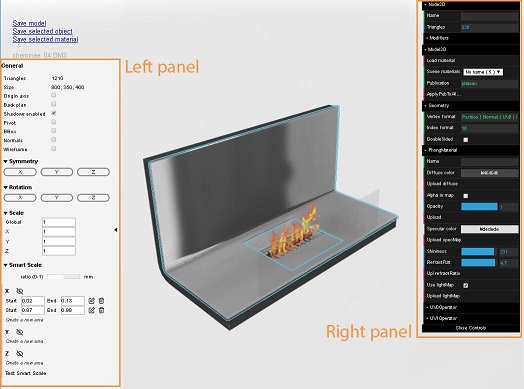
- Top left corner: Saving options.
- Left panel: Information, visualization and editing options related to the whole geometry.
- Right panel: Information and editing options related to selected 3D node and material.
Right panel varies depending on the type of material (Phong or PBR) selected in the scene.
Left Panel
Saving options
- Save model: Download scene as a BM3 file.
- Save selected object: Download selected Node as a BM3 file.
- Save selected material: Download selected material as a BM3MAT file.

General
The "General" menu provides information on the 3D model: total polycount, bounding box size.
It also allows to show or hide helpers in the scene:
- Origin axis displays origin axis
- Back plan displays a red plane at the back of the model's bounding box (helps to know if the model is correctly oriented)
- Shadows can be enabled or disabled
- Pivot displays the model's pivot, which is automatically set to the bottom center of the bounding box when importing a model in Geometry Editor
- BBox displays the model's bounding box
- Normals displays vertices normals
- Wireframe displays mesh triangulation

Symmetry, Rotation, Scale
- Symmetry: Flip model on X, Y or Z axis
- Rotation: Apply a 90° rotation on X, Y or Z axis
- Scale: Multiply scale by the value in the field on the whole model or independently on each axis

Smart Scale
For more details on the SmartScale concept, please refer
to ByMe Geometry and Materials Reference Document.
Smart Scale: Toggle to switch values from [0; 1] range and millimeters.
Create Smart Scale areas independently on each axis by picking start and end points.
It is possible to create multiple Smart-scalable areas on one axis. When doing so, the scaling ratio will be applied to
all areas.
Test Smart Scale: Allows user to test Smart Scale in a dedicated UI without really impacting the model.

Right Panel
The right panel is the main place to review and modify models in the ByMe GeometryEditor. The panel is divided into several folders as described below. Those folders are contextual and might not all be present on screen at the same time. The material menu for example will change depending on what type of material is currently selected.
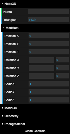
Node3D
The Node3D menu gives the user insight on the currently selected "node" or part of the displayed model.
The main informations are:
- Name: The name of the node if it exists.
- Triangles: The number of triangles of the geometry associated with this node.
- Modifiers: Sliders to modify the position, orientation and scale of a node.
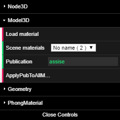
Materials and Publications
The materials and publications menu gives the user information about materials and material publications:
- Load material: A button that lets the user upload a .bm3mat from their computer to Geometry Editor, and applies it to the currently selected node.
- Scene materials: Lets the user select the material applied to the currently selected node from the list of materials that came with the model plus the ones loaded with the "load material" button.
- Publication: Lets the user set a material publication to the currently selected node.
- ApplyPubToAllModel: Applies the current publication to all nodes sharing the same material as the currently selected node.
Geometry
The Geometry menu gives the user some information on the geometry of the currently selected node:
- Vertex format: The way the geometry is stored in memory. Here the attributes are interlaced in a single buffer and the model has normals, position, UV0 and UV1 attributes.
- Index format: The size required in bits to store a single index in memory.
- Double sided: This box should be left unchecked.

PBR Material
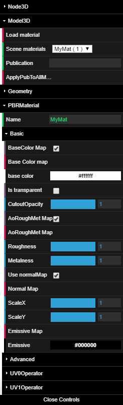
The PBRMaterial menu is shown if the currently selected node has a PBRMaterial attached. All the parameters can be
changed from this menu to modify the material.
The full parameter reference lies in the PBR Materials Supported Features section. We will however discuss a few specifics of the UI.
When a color has to be chosen, base color and emissive for example, the UI displays the color in sRGB color space. The conversion to linear space is handled by the software. The takeaway here is that you should choose the color you want to see in the end, and not think about color spaces.
The "is transparent" checkbox defines whether the object is treated as transparent or not. This is not a lightweight decision; transparent objects are expensive. That is the reason why if opacity is set to a value below 1 but transparent is not set to true your object will not be transparent.
ScaleX and ScaleY parameters allow you to control how much influence the normal map has on the geometric normal in the u and v directions of the relative tangent space.
The advanced folder is experimental and can be used to get a preview of features that might come later. These features are not documented and should not be expected to work.
Note (on roughness / metallic / occlusion maps):
One can either provide a roughness / metallic map with a separate ambient occlusion map or a single map containing the data in three separate channels: ambient occlusion in the red channel, roughness in the green channel and metallic in the blue channel. The only acceptable situation in which we allow the ambient occlusion to be in a separate map is that it needs its own set of UV.
For these reasons, the UI can change a bit depending on the situation. In this first picture we see that the AoRoughMet
Map box is ticked, meaning a single map containing the data for all three parameters is used.

Below, we can see that two different maps are provided: RoughMet Map and AO Map. In this case, the roughness metallic
map has an empty red channel and the ambient occlusion map is a grayscale one. It is also entirely possible to specify a
roughness metallic map if no ambient occlusion data is available or needed.

Phong Material
The PhongMaterial menu is shown if the currently selected node has a PhongMaterial attached. All the parameters can be changed from this menu to modify the material, add textures, features and so on.
The full parameter reference is in
the Phong Materials Supported Features section. We will
however discuss a few specifics of the UI.
When a color has to be chosen, base color and emissive for example, the UI displays the color in sRGB color space. The
conversion to linear space is handled by the software itself. The takeaway here is that you should choose the color you
want to see in the end and not think about color spaces.
The "Alpha in map" check box needs to be checked if the diffuseMap contains transparency.

The ShininessInMap checkbox needs to be checked if shininess has been set in the alpha channel of specMap.
UV Operator
UV Operator allows user to edit texture mapping settings of UV channel 0 and/or UV channel 1. The resulting computation
of this operator is
newUV = uv * scale + offset
The rotate parameter is in degrees and will rotate the UV basis clockwise around the normal, thus rotating the texture.

The scale parameter must match the physical length a texture represents. For example, if a texture represents 1m by 20cm
wood planck, the scales must be 1000 for X and 200 for Y. (see Importing Materials section
in ByMe Geometry and Materials Reference Document)