Step 5 – Introduction to Assembly Editor
The aim of Assembly Editor is to group together the components (3D products and non-3D items, with their parameters) into one finished product that can be displayed to the customer, while taking their relative placement and orientation into account. This finished product will be offered to the customer in the Kitchen Planner with a 3D experience that will allow her/him to manipulate the product, zoom in and out, try various combinations, and eventually edit the product to match it to her/his wishes.
The native format of Assembly Editor is .BMA. A .BMA file is a list of components that are placed according to a position mapping.
Assembly Editor also allows you to add kinematics (such as opening a door in the Kitchen Planner), manage component positioning (absolute or relative), manage component publication, manage output sets (for cut-out or worktop generation) and manage anchor points (possible positions of components in editable furniture).
📌 Assembly Editor allows you to work with .BM3 and .BMA files. The condition is that they have a datasheet in 3DCloud.
Vocabulary and Concepts
The aggregation of the components is named "assembly" hereinafter.
"Components" are products registered in 3DCloud.
The properties of each component (position, orientation, own parameters, etc.) can be linked (or "binded") to parameters and/or relations of the assembly: that is why these assemblies are named "parametric assemblies".
About Parameters
There are many parameters in Assembly Editor: they are the duplication of all the parameters defined in the 3DCloud datasheets. There are component parameters, size parameters, material parameters, etc. each parameter having a different type. A parameter can be a dimension (mm), a Boolean, an integer, a material, or a component.
Some parameters may be visible or editable by the customer in the Kitchen Planner, or by the Range Manager in 3DCloud.
About Relations
The default dimensions, for example, are recovered from the .BM3 file. They can be overloaded by dynamic values obtained through relations.
A relation make it possible to define calculated positioning of components – instead of fixed, absolute positioning. For example, legs are always positioned under the cabinet with the given offset; the relation can determine the position of the legs, whatever the width of the cabinet is.
Relations are expressions used to calculate dynamic values from parameters or other relations. A relation supports mathematic operators (such as + , - and * ) or logical tests (using a dot as separator). The result can be assigned to component properties, output set properties and anchor point properties. Relations are defined internally and cannot be overloaded, whether in 3DCloud by a Range Manager or in the Kitchen Planner by a user, to avoid structure problems.
➡️️ Refer to the Product and Assembly reference 🔗 documentation, section "Assemblies" for detailed information on the relations.
🚧 For our sample, we will define many relations to position the legs, the handle or the door front dynamically.
About Component Positioning
The positioning of the components can be of three types:
- Absolute, relating to the axes;
- Relative, via expressions.
➡️️ Refer to the Assembly Editor Reference 🔗 documentation for a complete information on anchor points.
About Kinematics
You can define in Assembly Editor the kinematics that can be played in the Kitchen Planner. These kinematics behaviors are either of rotation or of translation type.
❗ The scope of the animation cannot be on a single component of the assembly to which you want to add a kinematics, because it will apply on all the components. Therefore, you have to create the kinematics on the right level.
🚧 In our case, we want the door (i.e. front with the fixed handle) to rotate: we will put the kinematics on the sub-assembly containing the two components front and handle.
About Output Sets
An output set is a linear information required in specific cases to handle application features requiring 2D as an input. Specific cases are every linear products: worktop, plinths, cornices…
🚧 For our sample, we will define output sets to place the worktop on the base cabinet.
➡️️ Refer to the Assembly Editor Reference 🔗 documentation for a complete information on output sets.
About Sub- and Top-Assemblies
Sub-assemblies are a way to ease the work and make common configurations reusable. Each sub-assembly is then registered as a product and linked to a catalog in 3DCloud in order to be used either as such or as a component in a top-assembly.
For example, it is highly recommended to create a "legs and box" sub-assembly or a "front and handle" sub-assembly.
A top-assembly is the final assembly built from simple components and sub-assembly components. The top-assembly is then registered as a product and linked to a catalog in 3DCloud.
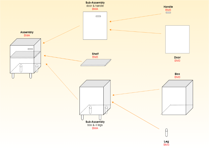
Datamodel
Below is an overview of the data model, where components are grouped into sub-assemblies before creating the final assembly.
We recommend creating sub-assemblies of the door front with the handle, and of the box with the legs. Then, add them to the top-assembly.
Quick Overview of the Interface
➡️️ Refer to the Assembly Editor Reference 🔗 documentation for detailed information on the User Interface.
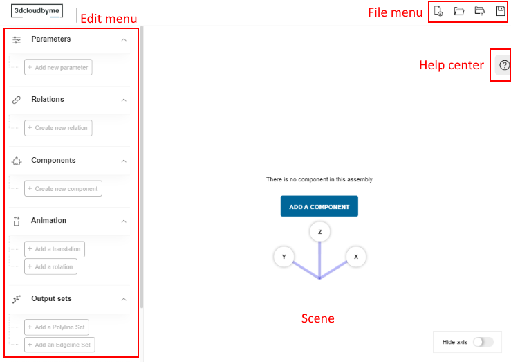
The workspace is organized into three areas.
- The File menu, from where you can create, open and save an assembly.
- The Edit menu, where you create the components, parameters, relations etc. for the assembly.
- The Scene, where you can view and manipulate the assembly.
- The Help center, which checks the validity of the assembly.
The File menu contain the following functions:
| Icon | Function | Description |
|---|---|---|
| New assembly | Click this icon to create a new assembly. This will close the current assembly, if applicable. | |
| Open from disk | Click this icon to open an assembly from your disk. This will close the current assembly, if applicable. | |
| Open from URL | Click this icon to open an assembly from an URL. This will close the current assembly, if applicable. | |
| Save | Click this icon to save the current assembly, even if it is not finished. This will create a zip file containing a root.BMA file, to save on your disk. |