Product Lights
Overview
In ByMe applications, scene illumination usually originates from ambient light. Products added to scenes, such as lamps, can be designed as decorative products. They can also be configured to emit light realistically, in order to add light effects in mixed illumination environments and purely artificial illumination scenarios. This section details how to add this capability to a Product.
Note: several aspects are detailed here in order to manage the significant computing costs of this feature ( computation of illumination, of shadows…). First, the number of light sources is limited by the application in order to maintain performance. Then, the rendering performance constraints being different in real-time applications ( rasterisation) and ray-tracing (“HQ”) applications, ByMe exposes dual settings for the same product, so that the asset author can create lights that are both efficient in real-time, and highly realistic in ray-tracing.
Concepts
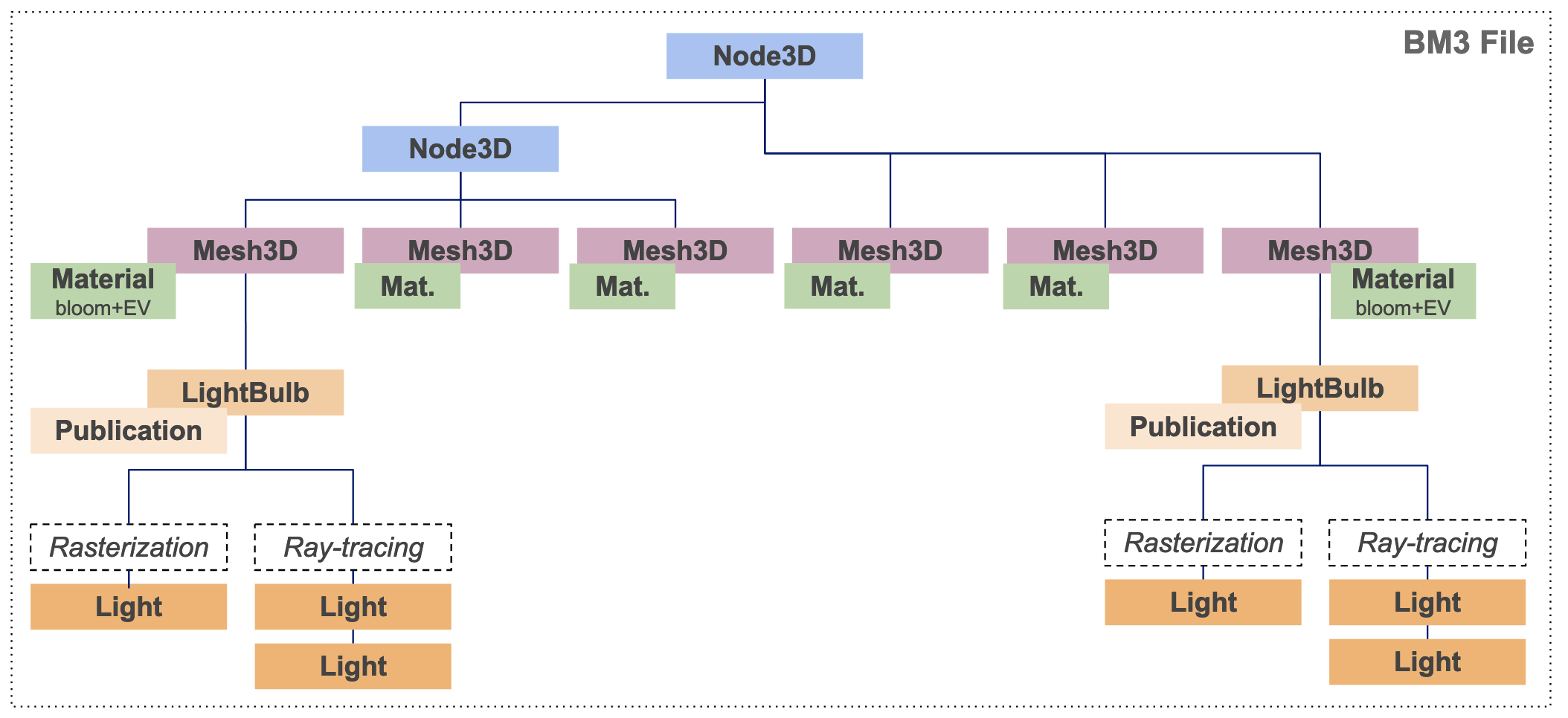
Adding lights on a BM3 : Bulbs
The following steps are performed in Geometry Editor.
Mesh prerequisites
The light emitting surface is a complete mesh node, representing for instance the surface of a lightbulb or a tungsten filament. This mesh needs to be split from other surfaces in the model, in the original 3D authoring software.
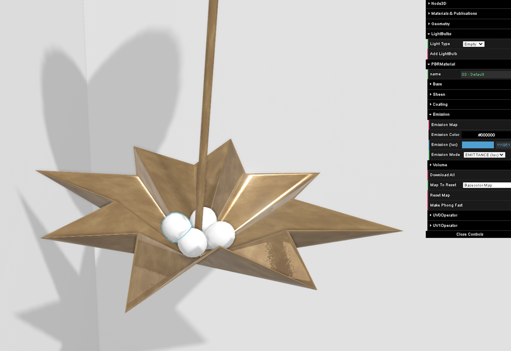
Add LightBulb
Click on this mesh in the 3D view, and then click “Add LightBulb” in the right-hand menu.
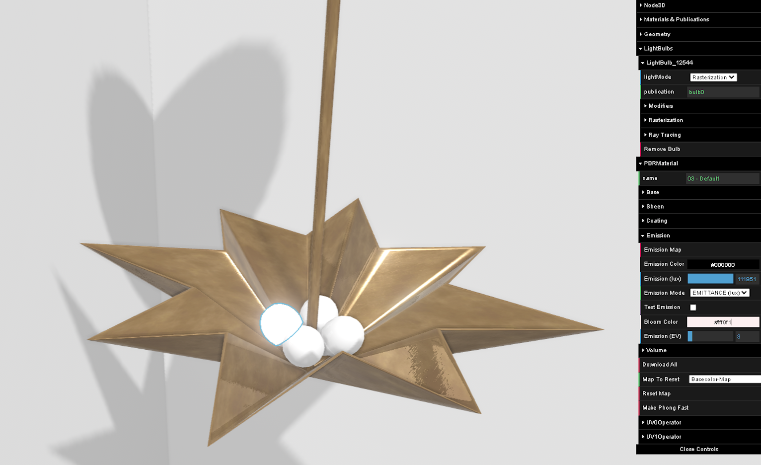
Publication
Set the name of the publication : this enables external control on this lightbulb from the application. The naming convention is bulb0, bulb1 etc.
- Give the same publication name to the different bulbs of a lamp that should be controlled together,
- and different publication names to bulbs (or set of bulbs) that are controlled independently.
Adjust material
Set the appearance of the illuminated node through the additional parameters in the PBRMaterial section : Bloom Color
governing the glow effect, and EV (exposure value) governing the whiter appearance of the node surface.
At this stage, bulbs do not yet emit light. This is the purpose of the following section.
Adding lights on a BM3 : Lights
This section details how to create actual light emitting sources within the bulb. To account for different scenarios, it is possible to add several lights to one bulb.
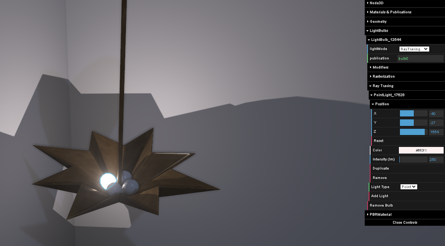
Activate Night Mode
Turn on the “Night Mode” by selecting “night” in Lighting Presets on the left panel.
Activate the light source representation by ticking “Display Lights”.
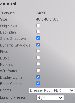
Setup rasterization lights
In the right-hand side panel, open “Rasterization” to setup the light sources for real-time applications. Click on “Add Light”, and then select Light Type :
- Spotlight : a cone,
- Pointlight : an isotropic light source.
Then fill the different parameters : position, direction, color, intensity (in Lumen).
For the spotlight, set the Inner Angle (half beam angle) where the full intensity stops and intensity starts decreasing,
Outer Angle where the dark begins. The constraints are the following : 0 <= Inner Angle <= Outer Angle <= 80°.
Colors for typical light sources are the following :
| Color temp (K) | Color | Source | Hex RGB |
|---|---|---|---|
| 2000K | very warm white | candlelight | ff6215 |
| 2700K | warm white | tungsten | ff8c3c |
| 3200K | warm white | halogen | ffa761 |
| 4000K | neutral white | LED | ffcea7 |
| 5000K | clear white | sun | f9f2ff |
| 6500K | cool white | clouds, neon | a3bfff |
Repeat for all 4 light bulbs in this lamp, with the cones oriented in 4 directions. This will result in better shadows than using a point light. For a table lamp with a shade, it is common to use a pair of spotlights, one wide cone facing downwards, and a narrower one facing up. This also results in softer shadows than a point light.
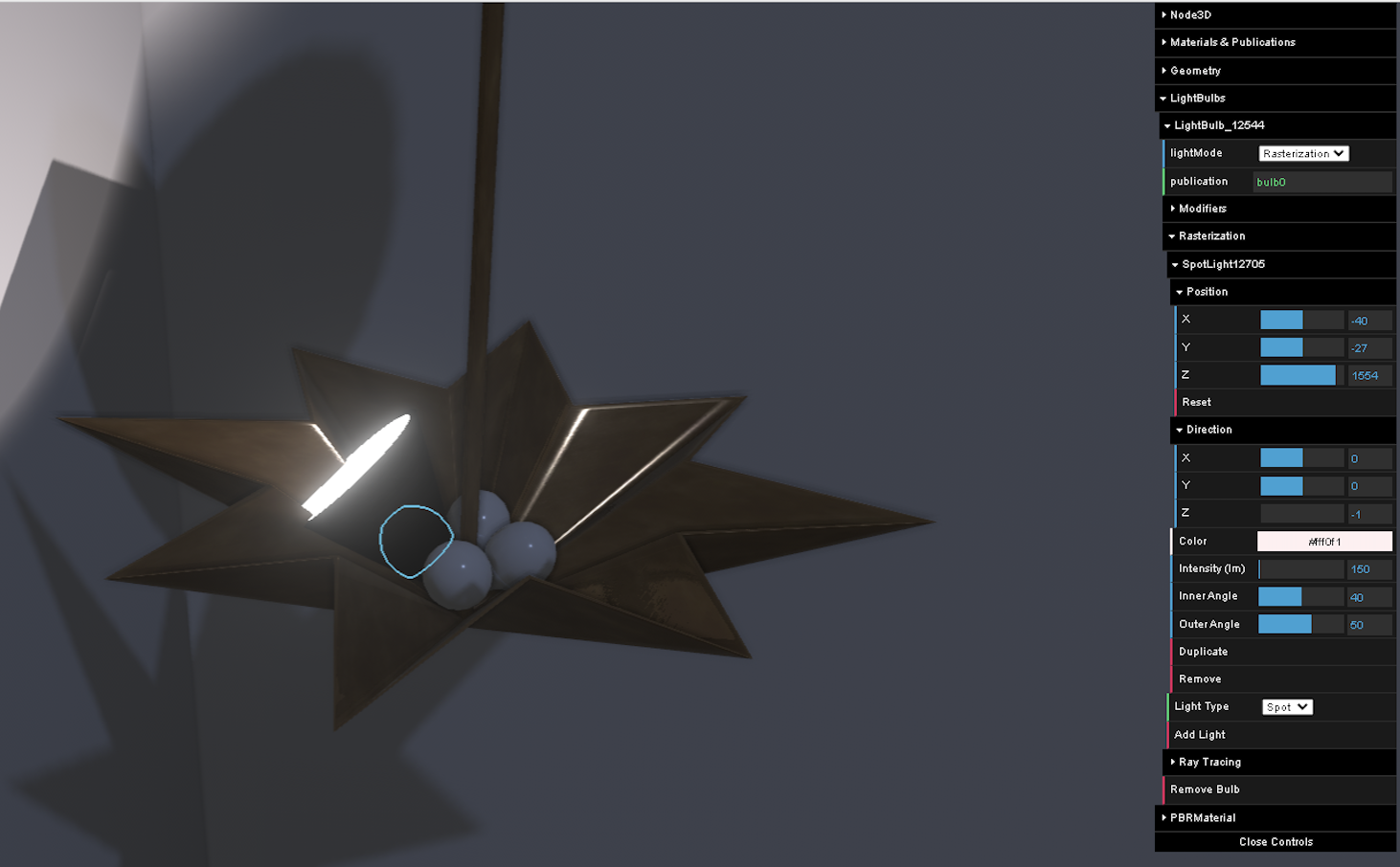
Setup Ray tracing lights
In the right-hand-side panel, open “Ray Tracing”. Add a light source. In the following example we use a point light,
emitting in all directions. This gives better results in ray tracing. This can be tested by publishing the product and
testing ray-traced (“HQ”) renders from within the application. Shadow artefacts can exist in Geometry Editor, based on
real-time rasterisation technology, which would not exist in ray-tracing.
Save the BM3 file and add it to a Product.
Give control to the user
Once the light-enabled BM3 is set onto a Product, the resulting effect can be observed in applications, which use the default light intensity and color set in the BM3. It is possible to go further and control the switch, the intensity and the color of the light, leveraging publications and parameters. These aspects can then be controlled by end-users.
The following steps are performed in 3DCloudByMe.
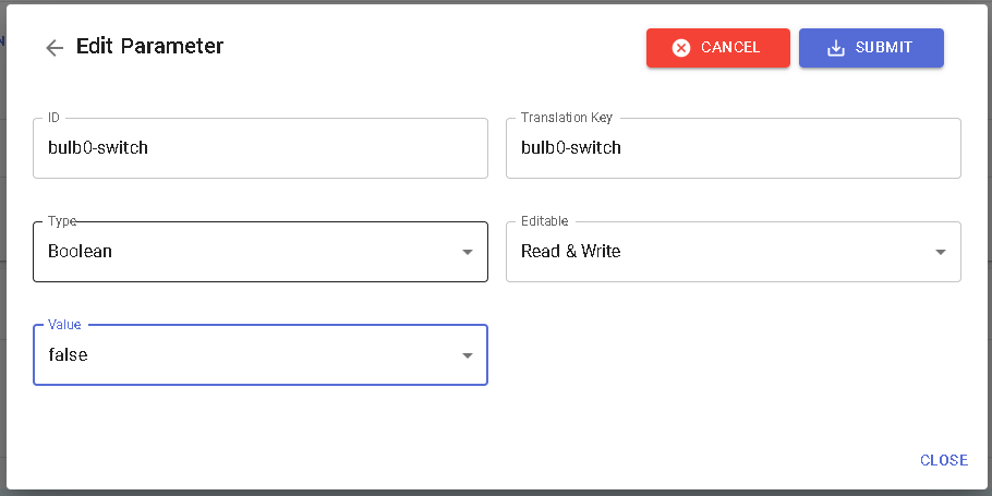
For each publication defined in the BM3 with the name “X", there is an implicit binding to the parameters named * X-switch*, X-intensity and X-color. Then set these parameters as visible and editable in order to expose them in the Product edit panel in the application.
The following example only controls switch and intensity :
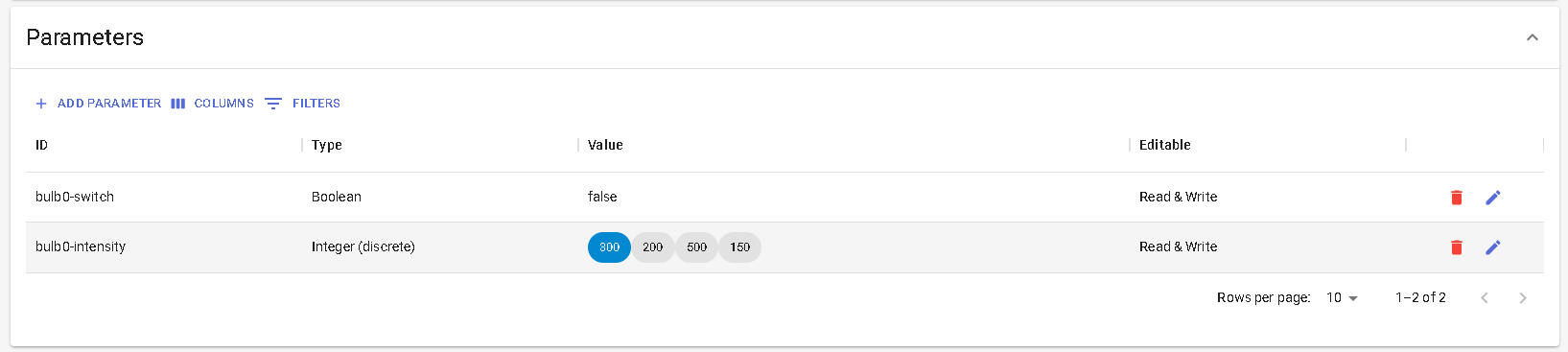
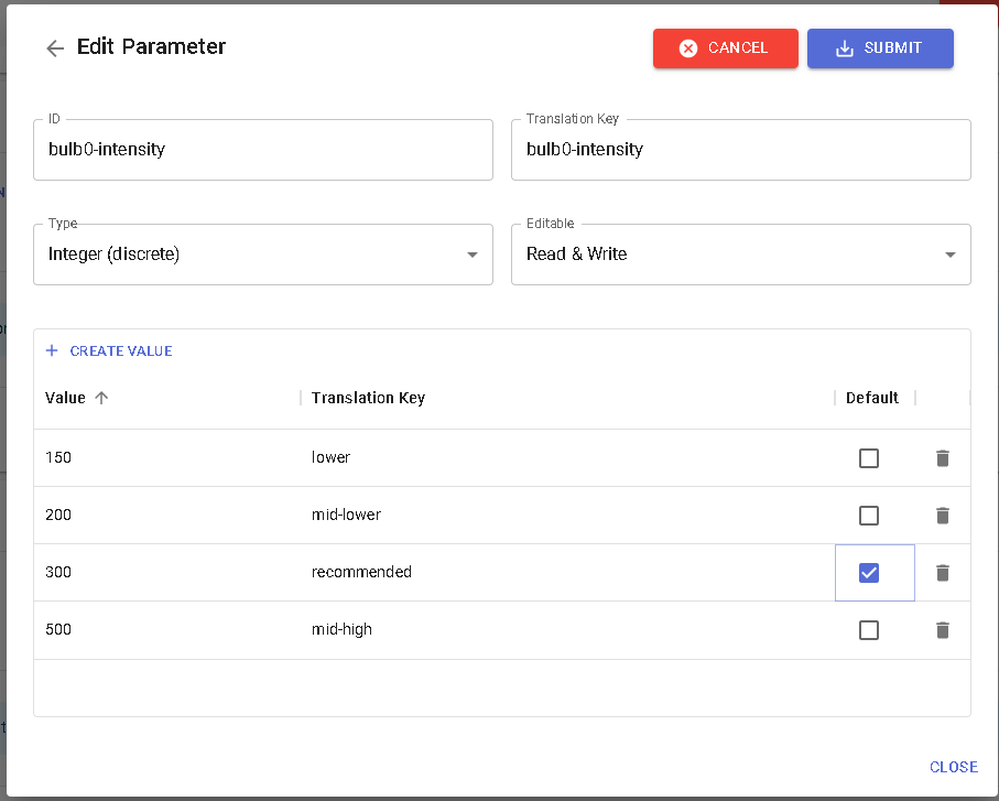
This example is based on the bulb0 publication name.
The intensity parameter is defined as a real parameter. In this example, there are 4 different intensities named through
translation keys :
The switch parameter is defined as boolean :