Create a Base Cabinet
Tutorial – From 3D objects to a marketable base cabinet
Introduction
Cabinets are the basic elements of a kitchen: they content objects, they support the sink, or they integrate an oven or a hood. There are four types of cabinets: base, wall, high and corner cabinet. Each type of cabinet can be customized to arrive to a choice of hundreds of different models for the customer.
Thanks to this documentation, you will know how to create a sample base cabinet and be able to create various models from it.
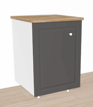
For our sample case, let us assume that our Range contains as best-seller a classical base cabinet with a black wood facade, a white knob, a natural wood top, four legs and a shelf inside. That this cabinet exists in two widths, with three possible worktops, a left or right-opening door, and a vertical handle in option, all this up to the customer.
We have to create the different parts of this cabinet, enable and define the variations, assemble the components to a piece of furniture matching with the real one, set the pricing, and finally add the cabinet to a catalog.
⬇️ Click here 🔗 to download the tutorial as PDF.
📌 The aim of this step-by-step documentation is to help you create a base cabinet manually. This might be a long proceeding if you want to add several cabinets and their variations to the database.
There is a way to deal with large catalogs, reduce delays and ease the global creation process by automating the most of it: by using the ByMe API and our libraries of 3D assets, assemblies and materials. Contact us for more information about this.
Pre-Requisites
To follow the complete process described hereinafter, you must have access to the applications with the appropriate rights.
You also need the following:
- Range information: Products, the corresponding 3D models, the 2D and 3D representations of them, a description, pricing and information about their behavior.
- Information about the Legal Entity to which the range belongs.
- An Application Distribution: This distribution is the way used by the platform to launch the planner in a certain context (e.g. for a specific language, a specific country, a specific set of catalogs).
Overview
The diagram below is an overview of the workflow to create a base cabinet, from the 3D assets until it is visible in the Company's Kitchen Planner for the customer.
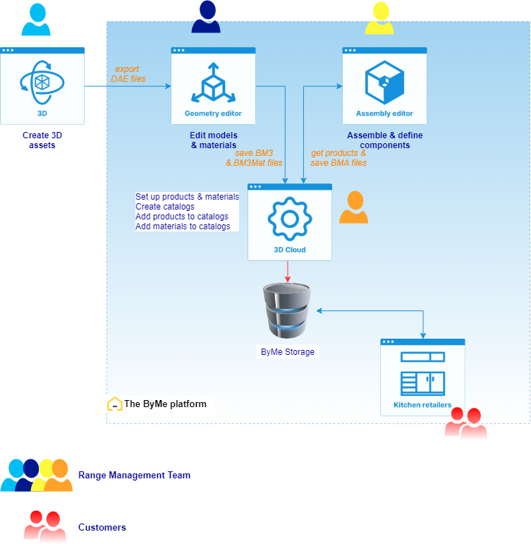
Although Geometry Editor, Assembly Editor, 3DCloud and the Kitchen Planner are inside the same solution, their user is not unique. Each ByMe application requires specific skills.
- Geometry Editor requires Designer skills;
- Assembly Editor requires CAD skills;
- 3DCloud, which is the front-end of the ByMe database, requires transversal skills: a Range manager with publishing workflow skills;
In the case of automated processes, the dialog with the database via the ByMe API should be done by a developer.
Terminology
➡️️ Refer to the Reference documentation of the ByMe platform for the complete list of the terms and concepts used in the applications.
Below is a short list of terms used in Geometry Editor and Assembly Editor. The table is ordered from content to container.
| Term | Definition |
|---|---|
| Geometry | The shape of an object, represented as a mesh of triangles. |
| Texture | A bitmap file contributing to the definition of a material. |
| Material | The representation of the visual properties of an object, such as color, shininess, reflexivity, etc. This representation is a BM3MAT asset. It can include several textures representing each of these properties. Linear products (worktops, cornices, strips, etc.) using materials as resources are generated by the application depending on the context. |
| Model | The combination of a geometry with one or several materials. It is stored in Geometry Editor as a BM3 binary asset file. |
| Product | The datasheet of a model in 3DCloud, which will be stored in the database with a unique ID. This sheet includes text descriptions, tags, an image that will be used as a thumbnail, a link to the BM3 or a BM3MAT or a BMA file, various parameters, etc. |
| Component | A building element of Assembly Editor, calling a product and its parameters. This component will be set to define additional or overloading parameters, and its positioning in the space. |
| Assembly | Leveraging traditional CAD notions, an Assembly is the aggregation of several components, specifying their relative positioning through precise parameters and relations. It is created and managed by Assembly Editor as a BMA asset file. |
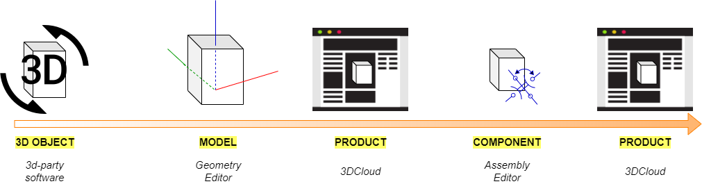
Note that the names change throughout the whole process, to illustrate their state change, as illustrated below:
Convention
🚧 This "under construction" icon indicates that the information relates specifically to the sample cabinet we are creating.