Step 5.a – Create the ‘Box and Legs’ Sub-Assembly
When starting a new assembly, the Edit 🔗 menu is empty.
Add the Components
Click Create new component on this menu, or click Add a component on the scene.
| From the Edit menu | From the Scene |
|---|---|
 |  |
Browse the catalog by specifying the name of the product in the search field. Use either the complete name as defined in the 3DCloud datasheet or the type e.g. "box" or "front". If you want to enter only the first letters of the name, add an asterisk to the name*. For example: "white_*".
Press Enter to start the search.
❗ If you do not find your product, check that it is linked to the catalog.

Click the thumbnail of the product to add it to the list of components and display it on the scene.
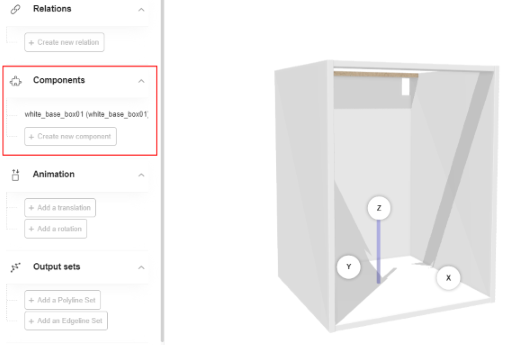
Repeat the proceeding to add the leg.You can show or hide a component on the scene by clicking the eye icon next to the component name.

Note that all the components are centered by default on the origin of the axes. Their final position is not yet defined.
Duplicate the leg three times by clicking the Duplicate icon, to obtain a set of four legs. At this stage, they receive a default name.

Rename the Components
Select a component in the list or on the scene to display its properties.
This area allows you among others to rename the component and define its position.
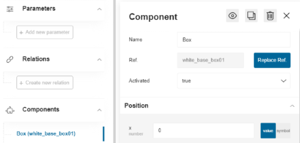
Rename the box component into "Box".
❗ Always capitalize the first letters of the words in a compound name to avoid confusion with parameter names. For example, a component name would be "CoverPanel" and a parameter name would be "coverPanel".
Rename each leg according to the diagram below:

Check that the components of the "box and legs" sub-assembly are all renamed.

Create Parameters
We highly recommend that you create parameters as things progress; avoid creating all possible parameters "once for all" to prevent confusions.
Create the Component Parameters
❗ Use camel case convention when renaming the parameters. Try to create meaningful names, as in our examples. Parameters always starts with a lowercase.
You have to create one parameter per component. Duplicated components are considered as a whole. For example, you have to create one parameter for the set of four legs.
To create a parameter, proceed as follows:
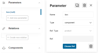
- Click Add new parameter in the Parameters area.
- Click the parameter to display its properties.
- Replace the default name by one matching the naming convention, e.g.
box. - Select component in the Type drop-down list. The associated reference type is specified automatically.
- Changes are saved automatically. Click the cross icon to close the Parameter panel.
🚧 For the "box and legs" sub-assembly of our sample cabinet, create the following parameters:
boxandleg.
Link the Parameters with the Components
The next step consists in linking each parameter to its component.
- Click the first parameter e.g.
boxto access its properties. - Click Choose ref to select a product reference to link with the parameter.
- Search for the product using its 3DCloud name. Then, click the product thumbnail to add it as reference.
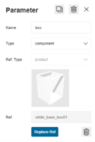
Repeat the proceeding to link the leg parameter with the leg product.
Now the component reference appears after the name, in parentheses, instead of "null".

Create the Size Parameters
❗ These size parameters are mandatory.
The next step consists in creating the size parameters of the box that will be useful for the sub-assembly.
- Click Add new parameter in the Parameters area.
- Click the parameter default name to access its properties.
- Rename the parameter into
width. - Select number in the Type drop-down list.
- Enter a value, i.e. 600 for the box.
- Repeat the proceeding with the height (800) and the depth (600).
The Parameters area now contains the following parameters:

Link the Size Parameters to the Box
This step consists in linking the size parameters with the dimensions of the components.
🚧 The box must be linked dynamically to the size parameters to prepare the scaling of the base cabinet.
Click the Box component in the list to consult its properties. Then, scroll down the panel to reach the **Overloads ** field. The size parameters displayed in this area are recovered from the 3DCloud datasheet.
- Select the check box regarding the depth of the component to enable the modifications.
- Move the cursor to Symbol to display the list of parameters declared in Assembly.
- Select the
depthparameter. The depth parameter of the Box product is now overloaded by the depth parameter of theboxcomponent.
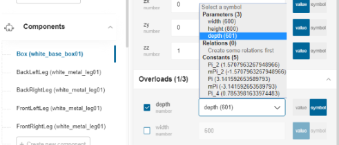
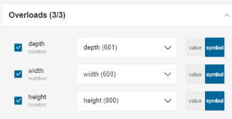
Repeat the proceeding with the width and height of the box. The Overloads area now indicates that the three parameters have been overloaded.
Define the Position of the Box in the Room
Each component is placed relating to the absolute coordinate system (origin and axis).
Click the box in the Components to display its properties. Go to the Position area to access the coordinates.
| Position sub-menu | Position on the scene |
|---|---|
 |  |
Keep 0 in the X and Y fields and enter 80 in the Z field. This value corresponds to the height of the leg. The box is now 80 mm higher from the floor.
Place the Legs
To position the legs under the furniture you have to consider the following:
- The size of the box;
- The positioning of the front legs on the box (may depend on whether the box will have a plinth or not);
- The positioning of the back legs on the box (the distance may not be the same as for the front legs);
Therefore, the position of the legs is managed through relations.
🚧 In our sample case, there is no plinth and the distance is the same for all the legs.
Create Leg Offset Parameters
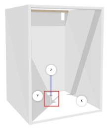
Before creating the relations, you have to create offset parameters to specify the position of each leg from the edge of the bottom of the bow. Then, these parameters will be used by the relations.
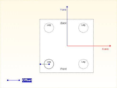
As illustrated above, the offset is the distance between the center of a leg and the edge of the box.
📌 Remember that our sample 3D objects are centered on the origin point.
There are four legs, thus you have to define four offset parameters:
- xFrontLegOffset: The offset of the front leg on the X-axis;
- xBackLegOffset: The offset of the back leg on the X-axis;
- yFrontLegOffset: The offset of the front leg on the Y-axis;
- yBackLegOffset: The offset of the back leg on the Y-axis;
To create these parameters, proceed as follows:
- Click Add new parameter in the Parameters area.
- Click the default name of the new parameter to display its properties.
- Replace the default name with
xFrontLegOffset. - Select number in the Type drop-down list.
- Enter a value, e.g. 100 if you want the center of the leg to be place 100 mm from the left edge of the box.
- Repeat the proceeding to create the three other parameters for the three other legs.
Now you have the following four leg parameters that you can use in relations.

Create Offset Relations
📌 Use the camel convention to rename relations; do not capitalize the first letter to avoid confusion with the components.
To create the relations, you do not have to consider the sides (front / back) but the axes (X and Y). Remember that the offset parameters are defined on these axes.
Thus, you will create four relations:
- Two relations to place the leg on the X-axis
- Two relations to place the leg on the Y-axis
These relations will get a value calculated dynamically through a formula. This is important to ensure that the legs are aligned on a given axis.
Click Create new relation on the left menu to start creating the relations.

- Select the default name of the relation to display its properties and start defining the relation.
- Change the default name with an appropriate one: xLeftLegsRelation.
- Select number in the Type drop-down list.
- Specify the Expression field with a formula referring to the main width parameter and specifying the distance in
millimeters from the edge of the box:
-width*0.5 + xFrontLegOffset. - Press Enter to save the expression and update the Value field.

Repeat the proceeding to create the second relation for the X-axis.
- Name the relation xRightLegRelation.
- Enter
width*0.5 – xBackLegOffsetin the Expression field.

Create now the relations on the Y -axis with the same proceeding. Note that the expression uses the depth parameter instead of the width, to be consistent with the Y-axis. Define them as follows:
| yBackLegsRelation | yFrontLegsRelation |
|---|---|
Use yBackLegOffset in the expression | Use yFrontLegOffset in the expression |
|  |
Define the Position of each Leg
Now that the relations between the legs on a same axis and the box are created, you can specify the XYZ position of each feet from the floor.
Click the BackLeftLeg component in the Components list to display its properties. Go to the Position area.
📌 For the case you would define a fixed position for the legs, remember to take both the width of the box and the offsets into account. In addition, remember that the components should be distributed from the origin point.
With the perspective of the future scalability of the cabinet, we will define dynamic positions of the legs, using the relations we have created previously.
| Process | Screenshot |
|---|---|
| For our sample cabinet, which width and depth are 600 and 600 respectively, enter the following: • X position: Move the cursor to Symbol and select the xLeftLegsRelation. • Y position: Move the cursor to Symbol and select the yBackLegsRelation. • Z position: Enter 0 (legs are on the floor). | 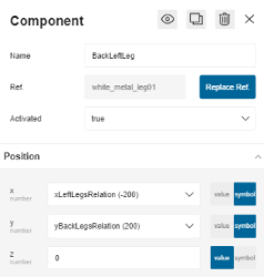 |
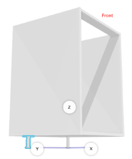
The back left leg is now placed as illustrated below:
| Bottom view | Side view |
|---|---|
 |  |
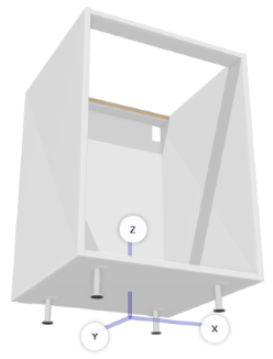
Repeat the proceeding to place the three other legs and obtain the following result.
| Back Left Leg | Back Right Leg | Front Left Leg | Front Right Leg | |
|---|---|---|---|---|
| X position | xLeftLegsRelation | xRightLegsRelation | xLeftLegsRelation | xRightLegsRelation |
| Y position | yBackLegsRelation | yBackLegsRelation | yFrontLegsRelation | yFrontLegsRelation |
| Z position | 0 | 0 | 0 | 0 |
| Bottom view | Side view |
|---|---|
 |  |
Prepare the Worktop
The availability of the worktop is ensured by the combination of the worktop option and output sets. Should one of these be missing, the worktop could not be generated in the Kitchen Planner.
❗ Do not add the worktop as material or component in Assembly Editor, this is useless. The worktop is added dynamically to the base cabinet in the Kitchen Planner only. See below "Step 7 – Display the cabinet in the Kitchen Planner".
Worktop Option
The worktop option is set in the top-assembly datasheet.
➡️️ See Step 6 / worktopOption for the proceeding.
About Output Sets
An output set is a linear information required to place the worktop on the base cabinet. In the Kitchen Planner, output sets are used to define the 2D properties of the worktop (and plinths, wall panels, decorative strips, cornices paths as well).
Output sets are of two types:
- A polyline set, which is limited to lines defined by points only;
- An edgeline set, which allow lines and circles defined by points and radiuses.
🚧 To define the position of our worktop, we will use polyline sets.
Create the Relations
Polylines have either fixed coordinates, or variable coordinates using relations, in the perspective of a scaling.
Place the starting point of the polyline, through a first relation.
- Click Create new relation.
- Click the default name to display the properties.
- Rename the relation into xPoint0NarrowPathPosition.
- Select number in the Type drop-down list.
- Go to the Expression field.
- Enter a formula referring to the width parameter
width*0.5as illustrated below. Press Enter to save the expression and update the Value field above.

Then, place the destination point through a second relation named xPoint1NarrowPathPosition , which formula
is -width*0.5.

Create the Output Set
The points are created through the relations; you will now create the lines between these points and place them.
Scroll down the left menu to Output Sets and click Add a polyline set to create the first output set.

-
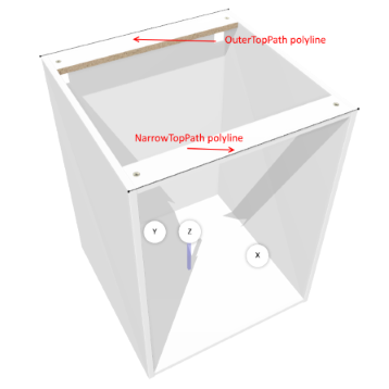
Click the default name to access the properties and rename it into narrowTopPath. "Top" means that this path concerns the top of the base cabinet; "narrow" means the front of the cabinet.
-
Click Add a polyline to specify that you will draw a line. You cannot rename the polyline.

-
Click Add a point to specify the start point of the line, and repeat this step to create the final point of the line. You cannot rename the points.
-
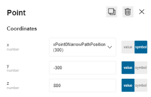
Click the first Point (0, 0, 0) to access the coordinates of the start point. You could enter fixed coordinates but we will use the relations created previously.
-
Move the cursor to the right of the X field to Symbol , to display the list of relations.
-
Select xPointONarrowPosition in the list.
-
Enter values in the Y and Z fields, because the scaling of the cabinet is limited to the X-axis: a. Enter -300 in the Y field , this value being the half of the depth of the box; b. Enter 880 , in the Z field, this value being the total height of the cabinet (box and legs).
Do not worry if a line appears across the box. The second point is not defined yet.
Click this second point and repeat steps 5 to 7 to define it with the following values:
| Values | Screenshot |
|---|---|
| • X field: The xPoint1NarrowPathPosition relation • Y field: -300 • Z field: 880 |  |
The first outline is now specified.
Repeat the whole proceeding to define the second polyline.
- Scroll down the left menu to Output Sets and click Add a polyline set to create a second output set.
- Rename it into outerTopPath. "outer" means the back of the cabinet.
- Click Add a polyline.
- Click Add a point twice to add two points. You cannot rename the points.
- Click the first Point (0, 0, 0) and specify the following coordinates.
- X field: select the xPoint0NarrowPathPosition relation
- Y field: enter 300 (i.e. the half of the depth of the box)
- Z field: enter 880 (i.e. the height of the box plus the legs)
- Click the second Point (0, 0, 0) and specify the following coordinates.
- X field: select the xPoint1NarrowPathPosition relation
- Y field: enter 300 again
- Z field: enter 880 again
The output sets are now defined as illustrated below. The box is ready to receive a worktop in the Kitchen Planner.
Save the Box and Legs Sub-Assembly
Following the data model, (see above Data Model) the box and the legs must be saved as a sub-assembly. This is recommend to make it reusable and necessary to make them work as a group in further animations.
Save the Work
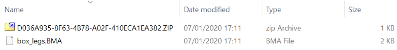
Click the Save my work icon on the up right corner to save the sub-assembly as a .BMA file. Assembly Editor produces a zip file containing a root.BMA file. Move the zip file to your project location and rename the file into box_leg.BMA.
Create a Datasheet
Then, create a product datasheet in 3DCloud for this sub-assembly. Import the .BMA file as 3D Model representation.
You have to define in the 3DCloud datasheet all the parameters that are defined in Assembly.
🚧 For our "box and legs" sub-assembly, this means that you have to create the size parameters (W600 / D600 / H800) and the offset parameters.
Finally, add the new product to the catalog.
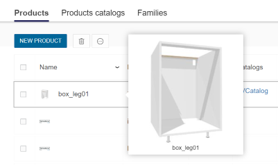
Whereby, you will be able to import it as a component in Assembly Editor to continue building the base cabinet.