Step 2 – Work with Geometry Editor
The second step consists in importing the 3D object files into Geometry Editor, edit them (i.e. define which areas will be scalable and/or act on materials among others) and then, convert them to the Geometry file format.
These files are preferably in .DAE format, but it may be:
- .GLB files;
- A folder containing either a .BIN + a .GLTF + the required textures;
- A folder containing an .OBJ file + one or more .MLT files + one or more textures;
- A folder containing a .DAE file + an image folder.
➡️️ See Appendix 3 / Analyze the supported features 🔗 for further detail.
Import 3D files into Geometry Editor
To import files, proceed as follows:
- Connect to 3DCloud , the UI of the ByMe database.
- Scroll down to 3D Tools and right-click to open Geometry Editor in a new tab.
![]()
- Open Finder or the Windows Explorer to search for the .DAE file corresponding to the first model that you want to open in Geometry Editor.
- Drag and drop it to the Editor tab. The 3D representation of the model is now visible, you can manipulate and edit it.
Quick Overview of the Interface
➡️️ Refer to the ByMe Geometry Editor Reference 🔗 documentation for detailed information on the User Interface.
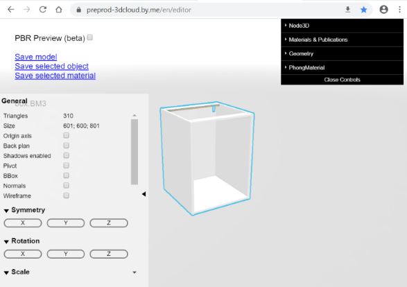
The workspace is organized into four areas.
- The scene, which is the 3D representation area where you can manipulate the model.
- A left grey panel, where you can visualize and edit various options for the whole geometry.
- A right black panel, where you can visualize and edit options for the selected 3D node or material.
- A Save menu, depending on what is selected in the scene.
The Black Panel
🚧 The black panel is where you define material variations.
Select a node on the model to expend the menu, then expend each menu item to access the options.
Some options on the black panel have borders: options with a red border allow you to select a file; with green borders to enter text; with blue borders to enter numeric values.
The content of the black panel varies depending on the type of material (Phong or PBR) that is selected on the scene.
The Grey Panel
🚧 The grey panel is where you define scalable areas.
You can customize the workspace by selecting some of the settings in the General area. For example, check the * Origin axis* box to display the X, Y and Z-axis.
The Save Menu
This menu offers three options:
- Save model: Save the whole model as a .BM3 file.
- Save selected object: Save the selected node as a .BM3 file.
- Save selected material: Save the material (or the material of the selected node) as a .BM3MAT file.
Edit 3D Models
The ByMe platform allows the dynamic modification of models (i.e. the model displayed to the user can be different from the 3D model file) by a Range Manager in 3DCloud, or by the customer in the Kitchen Planner.
Editing a model is essential if you want to create product variations. These variations might be to change the dimensions of the product or to change the material of the product.
| Variation | Name | Description |
|---|---|---|
| Enable size variation | Scaling | Increase or decrease the size of the objet while keeping the ratio between the three dimensions (height, width, depth). |
| Smart scaling | Make an area be stretchable on an axis. | |
| Change the color/material | Publication | Allows defining a face (i.e. a group of triangles) by an ID to be able to change applied material or color on this face via a parameter.Applied material shall be in .BM3MAT format. |
Smart-Scaling
➡️️ Refer to the ByMe Geometry and Materials Reference 🔗 documentation for detailed information on scaling, especially "Preparing geometries and materials for variability".
It is possible to scale geometries, either uniformly on each axis (default scaling) or non-uniformly, the smart-scaling working independently on each axis. However, smart-scaling is incompatible with curved or round shapes.
You can set a smart-scaling to allow the customer make changes in the Kitchen Planner such as enlarging the cabinet.
❗ To avoid scaling artifacts, a model supporting smart-scaling must have mesh edges all along the limit between stretchable and non-stretchable areas. Meshes that have been decimated / simplified will not guarantee this property and thus, will work poorly with smart-scaling.
🚧 For our sample cabinet, we will have to define a non-uniform scaling to allow the customer choose between two widths. The box, the door front and the shelf will be stretchable on the X-axis.
Material Publication
➡️️ Refer to the ByMe Geometry and Materials Reference 🔗 documentation for detailed information on preparing 3D assets to work properly and materials to remain homogeneous after publication.
Changing a material on an object or a part of it can be triggered by a parameter value change originating in 3DCloud (or the API), a product rule or the product edit panel of the Kitchen Planner.
A publication is a two-step action:
- In Geometry Editor: Assign a publication to editable nodes of the product.
- In 3DCloud: Add the matching material variation parameters.
🚧 For our sample cabinet, we can define a publication for the knob and the shelf.
Save the Files
Saving models and materials in Geometry Editor generates the following file formats.
| File format | Description |
|---|---|
| BM3 | The native format for 3D assets, containing a mesh of vertexes, parametric scale where appropriate, geometries, embedded materials and textures. In addition, save as models (.BM3 files) the items that do not require 3D nor variations, such as the legs. |
| BM3MAT | The native format for materials. It stores materials definition and textures, as well as ByMe additional concepts like UVOperators. |
📌 Models and materials are editable in the database through the 3DCloud User Interface.
Sample Cabinet
To create our sample cabinet, you should have the following objects.
| BM3 Files | BM3MAT file |
|---|---|
| A box A door front A handle and a knob A leg A shelf | A worktop |
Check List before Editing
If you want to duplicate a model to change its material or color, we highly recommend to save them as different models and not as a unique model with variations. For example, we will create a white knob from the metal one to have two knob models.
| Model & Material | Scaling | Description |
|---|---|---|
| Box | ✔️ Yes | Enable scaling for further width change |
| Door | ✔️ Yes | Enable scaling for further width change |
| Knob | ❌ No | Change the material to create a second knob |
| Metal Handle | ❌ No | |
| Leg | ❌ No | |
| Shelf | ✔️ Yes | Enable scaling for further width change |
| Worktop | ❌ No | Linear material |
📌 You do not have to start with a product in particular; there is no hierarchical order between the products in Geometry Editor. However, there is a tree structure in Assembly Editor.
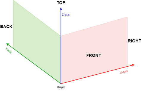
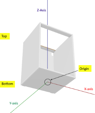
About the Axes
Geometry Editor offers a 3-dimensional view of the model. Scaling will be made on these axes.
You can display the axis on the scene by selecting the Origin axis check box in the General area.
Important: The origin point has been defined when creating the 3D object. In our sample, object are centered on the origin point. This will be important in Assembly Editor, when defining the positions of the different components.
📌 Select the Back plan option to be sure that the model is well located in the space.
About the Dimensions
The General area on the left panel gives essential information about the object:
- Triangles : The number of meshes of the 3D object.
- Size : The dimensions of the object, according to its positioning on the axes.
| Axis | Dimension | Value |
|---|---|---|
| X | Width | 600 |
| Y | Height | 800 |
| Z | Depth | 600 |
📌 For performance reasons, the ByMe platform encourages low poly assets.
➡️️ Refer to the Geometry and Materials Reference 🔗 documentation for detailed information on "Large Models, LOD and Simplification".
About the Ratio
The Scale fields, used to stretch a whole axis and not a part of it, are expressed as a ratio. By default, the * Smart Scale* fields are expressed as a ratio too.
| Scale | Smart Scaling |
|---|---|
 |  |
The ratio is calculated from the actual size of the object, which is "1". Therefore, to double a dimension on an axis, enter 2; to reduce by a half, enter 0.5.
When defining a Smart Scaling area, choose to work with millimeter values by switching the white Ratio cursor to the right.
About the Scalable Areas
When you stretch uniformly a whole object, the stretch area includes the side panels in the case of a box, or the molding in the case of a door.
To keep the size of these parts, you have to define scalable areas. This will define non-scalable areas by exclusion.
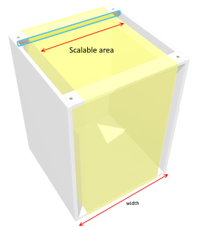
This illustration shows a basic cabinet with top-holes to fix the worktop on it and back-holes to fix the cabinet to the wall. The scalable area should exclude:
- The left and right panels of the box
- The top and the back-holes The illustration shows in yellow the area that should be defined as scalable. Outside this yellow area, all will be excluded from the scaling.This means that you only have to enter the start and end positions of the scalable area.Move the object on the scene to be sure to locate all the parts to exclude.
❗ Define the positions of the scalable area carefully to ensure the behavior in Assembly Editor.
Edit the Box to Define Scaling
Our work on the box is to define scaling to allow the widening of the box, which default size is 60 cm, to 80 cm.
Important: The box will not be stretched uniformly (this would increase or reduce the whole box including the side panels among others) but on the X-axis only and inside the concerned area to keep the thickness of the panels. That is why the dimensions will be set in the Smart Scale area.
To define the scaling, proceed as follows:
- Scroll down in the left panel to the Smart Scale area.
- Choose to express the dimensions in millimeters. By default, the fields are specified with the dimensions of the box.
- Click the View button to display the scalable area in yellow. By default, the whole box is included in the area.
 Now you have a choice between entering the values manually and using the mouse.
Enter the Values Manually
If you already know the values, enter them in the X input fields. The area should exclude the side panels, the holes on the top and the holes on the back. For our example:
- Enter 71 in the Start field. This is where our scalable area starts on the X-axis.
- Enter 534 in the End field. This is where our scalable area ends on the X-axis.
Click to Define the Values
If you do not already know the values, you can define them by clicking them on the scene.
- Use the mouse wheel to zoom in the object on the scene.
- Click the Edit icon on the right. This opens a Pick up area.

- Click with the left button of the mouse where you want the scalable area to start.
- Click with the right button where you want the scalable area to finish.
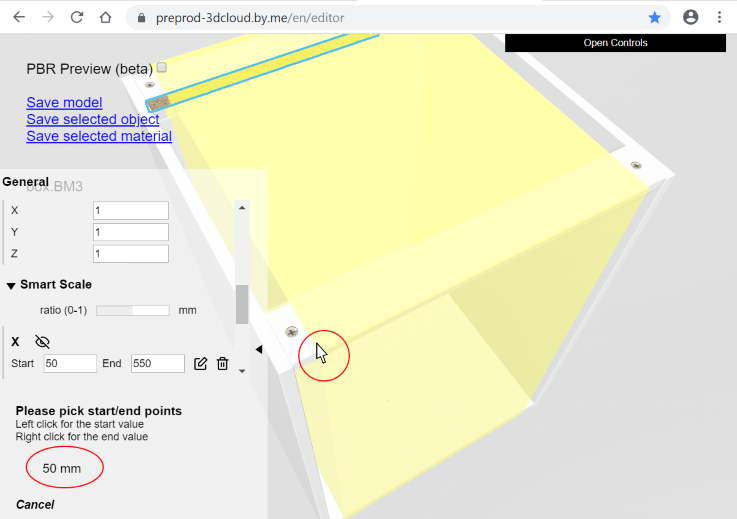
- Click Cancel to exit from the pick-up area. The new values are taken into account.
📌 Using the mouse to define the area can be very precise: the exact position in millimeters is displayed while moving the mouse. However, it is recommended to adjust values by rounded, symmetric and coherent numbers.
In the case you want to define several scalable areas on an axis, you have to add lines to the X area by clicking * Create a new area*.

Test the Scaling
You can test the scaling by clicking Test Smart Scale on the bottom of the grey panel.
Go to Scale and enter a value in the X field, e.g. 1.5 to stretch to 50% more, or use the arrows to increment the value.
Save the Changes
Click Save model to save the box and its scaling parameters as a BM3 file.
📌 The variation from 60 cm to 80 cm will be defined in 3DCloud.
Edit the Door Front to Define Scaling
Our work on the door front is to define scaling to enable a width variation of the central panel on the X-axis, excluding de facto the frame and the moldings.
The dimensions of our sample door are width 598 / depth 20 / height 798 mm.
| Process | Smart Scale area |
|---|---|
| To define the smart scaling, proceed as follows: 1. Scroll down in the left panel to the Smart Scale area. 2. Choose to express the dimensions in millimeters and click the Eye icon. By default, the whole surface will be in the area. 3. Click the Edit button to pick up the values to reduce this area. 4. Zoom in and click left to define the start value along the left molding. In our case, the value is 94. 5. Click right to define the end value along the right molding. In our case, the value is 305. 6. Click Cancel to exit from the pick-up area. The new values are taken into account. 7. Test the smart scaling if you want. | 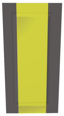 |
Save the Changes
Click Save model to save the door and its scaling parameters as a BM3 file.
Edit the Knob to Create a Duplicate
You may want to create a variation of a model, e.g. the same knob with another material and another color. The knob is made of two nodes (the nodes are defined during the modeling) and we will make a publication on the node corresponding to the button.
| Original Knob | Duplicate Knob |
|---|---|
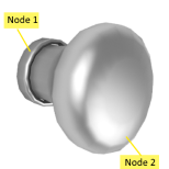 | 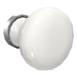 |
To create a duplicate of the metal knob, proceed as follows:
- Click the button on the scene to select it as Node3D.
- Specify a name if you want (press Enter to validate).
- Go to Materials & Publications.
- Click Load material to open the Finder or the Windows Explorer and search for the BM3MAT file corresponding to the new material. For example, a white acrylic material file.
- Click Open to load the file and add it to the list of choices named Scene materials.
- Rename the material if need be by specifying the Name field in the PhongMaterial area (press Enter to validate).
The Scene material drop-down list now contain a White Acrylic variation:

If you want to change the material of the ring, select the corresponding node and then proceed as for the button.
Save the Changes
Click Save the model to save the changed knob and its parameters as a .BM3 file.
Now, you have two different knobs at disposal.
Edit the Handle to Save it as Model
There is no scaling or publication work to do in Geometry Editor with the metal handle.
But you have to save it as a .BM3 file in order to import it in 3DCloud at the next step. Click Save model.
Edit the Shelf to Define Scaling
The work on the shelf is to enable the scaling on the X-axis, as for the box and the door. In addition, you might want to change its color.
Because there are no areas to exclude for the shelf, you can define a simple scaling.
- Scroll down in the left panel to Scale.
- Specify the X field with a ratio of 1.33 to stretch the shelf to 33% more on the X-axis.
📌 You can change the color of the shelf only if the model is a .SVG file or if the material has no texture. Else, change the material (see above the proceeding with the knob).
To change the color, proceed as follows:
- Select the object on the scene, to select the node on the black panel.
- Scroll down to PhongMaterial.
- Roll over the Diffuse color field to display a color palette.
- Pick up the wished color.
- Change the Specular color in addition if need be.
Save the Changes
Click Save the model to save the shelf and its parameters as a .BM3 file.
Edit the Worktop
The worktop is a linear material, i.e. a .BM3MAT file. As a linear, it is stretchable by definition and there is no scaling to define.
The substitution of one worktop by another will be set in 3DCloud.
You might want to change the tiling operator. In this case, scroll down the black panel to UVOperator and change the ScaleX and ScaleY values to adapt them to your needs. The tiling is expressed in millimeters.
Save the Changes
Click Save selected material to save the worktop as a .BM3MAT file.
Save the Leg as BM3
There is no edition work to do on the legs, but it need to be converted into a .BM3 file to be used as product and then component in 3DCloud and Assembly Editor.
Drag and drop the leg 3D model in Geometry Editor and then, click Save as model.