Step 5.c – Create the Top-Assembly
Following the datamodel, the sub-assemblies and the shelf must be grouped together in a top-assembly.
Import the Sub-Assemblies as Components
Now that both sub-assemblies are created and registered as products in 3DCloud, we can add them to a new assembly to be a part of the future top-assembly.
Create Components
- Click Create new component on the left menu, or click Add a component on the scene.
- Browse the catalog by specifying the name of the "box and legs" sub-assembly in the search field, i.e. *
box_leg01*. Press Enter to start the search.
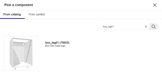
- Click the thumbnail of the product to add it to the list of components and display it on the scene.
- Repeat the proceeding to add the "front and handle" sub-assembly. Now you have the following two components.
- Rename the box_leg01 component into BoxWithLegs and the front_handle into FrontWithHandle.
❗ Always capitalize the first letters of the words in a compound name to avoid confusion with parameter names.

Component Parameters
❗ Use camel case convention when renaming the parameters.
You have to create one parameter per component, even if the component is a sub-assembly.
🚧 Actually, the only important parameter in our case is "handle" because this is the only component that we want the customer to control (when replacing the default handle with another one in the Kitchen Planner).
To create a parameter, proceed as follows:
- Click Add new parameter in the Parameters area.
- Click the parameter to display its properties.
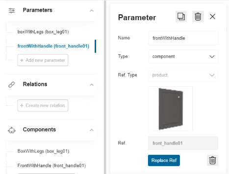
- Change the default name into
boxWithLegs. - Select component in the Type drop-down list. The associated reference type is specified automatically.
- Click Choose Ref to select a product reference to link with the parameter.
- Search for the product using its 3DCloud name. Then, click the product thumbnail to add it as reference.
Changes are saved automatically. Repeat the proceeding to create a frontWithHandle parameter.
You now have the following parameters.
Size Parameters
The next step consists in creating the size parameters for the sub-assemblies. Even if they have been specified at the creation, this is a new project and you need to specify the size parameters again.
Create the Size Parameters
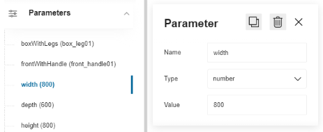
- Click Add new parameter in the Parameters area.
- Click the parameter default name to access its properties.
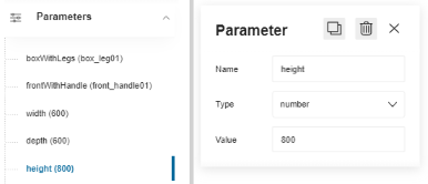
- Rename the parameter into
width. - Select number in the Type drop-down list.
- Enter a value, i.e. 600 that is the width of the future base cabinet, determined by the width of the box.
- Repeat the proceeding with the height (800) and the depth (600). The Parameters area now contains the following five parameters.
Link the Size Parameters to the Door Front
This step consists in linking the parameters of the product to those of the components.
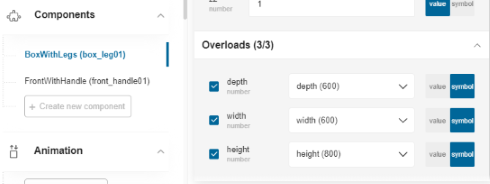
- Click the BoxWithLegs component in the list to consult its properties.
- Scroll down the panel to reach the Overloads field. The size parameters displayed in this area are recovered from the 3DCloud datasheet are displayed in a drop-down list.
- Select the check box regarding the depth of the component to enable the modifications.
- Move the cursor to Symbol to display the list of parameters declared in Assembly.
- Select the
depthparameter. The depth parameter of the "box and legs" product is now linked to the depth parameter of the "BoxWithLegs" component. - Repeat the proceeding with the width and height of the door front. The Overloads area now indicates that the Overload Editor contains three parameters.
Repeat the proceeding with the **FrontWithHandle component to overload the width of the component with the width parameter. Leave the other sizes as such.
🚧 Both "box and legs" and "door front and handle" combinations must be linked dynamically to the width parameter to prepare the scaling of the base cabinet on the X-axis.
Place the Shelf
The next step consists in placing the shelf inside the box, centered vertically. Take the height of the box into account (800 mm) and the position of the box from the floor (80 mm).
Start by creating a new component with the shelf of the catalog as resource, and rename it into Shelf.
The shelf is placed by default on the bottom, as usually.
Define the Position of the Shelf
Define now the position of the shelf on the X, Y and Z axes.
- Select the Shelf component in the Components list to access its properties.
- Go to the Position fields.
- Leave the X and Y position fields blank.
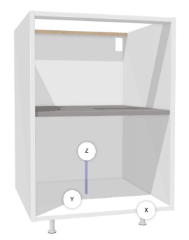
- Enter 480 in the Z position field, which is the half of the height of the box plus the height from the floor.
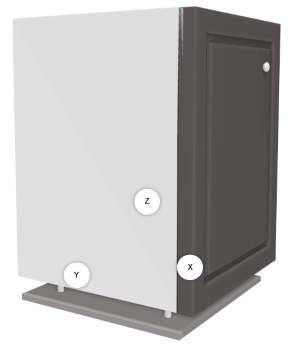
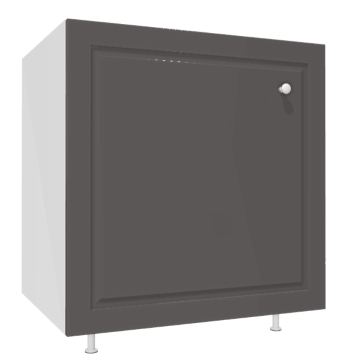
The shelf is now placed in the box, as illustrated below:
💡 To view the shelf in the box, click the eye icon of the FrontWithHandle component to hide it.
Shelf Width Relation
To enable the scaling of the shelf with the whole cabinet, the width of the shelf must call a relation between its own size and the main width parameter.
📌 Do not create specific width parameters because this would dissociate the shelf from the box when scaling it.
Thus, you have to create a relation that will reduce the global width recovered from the width parameter to adapt it to the shell.
- Click Create new relation.
- Click the default name to display the properties of the relation.
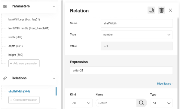
- Rename the relation into shelfWidth.
- Select Number as type.
- Enter
width–26in the Expression field (without any space). This updates the Value field above: the width of the shelf is now 574 mm.
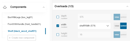
Link the Width of the Shelf to the Relation
This step consists in overloading the default width parameter recovered from the datasheet with the value of the relation.
- Click the Shelf component in the list to consult its properties.
- Scroll down the panel to reach the Overloads field.
- Select the check box regarding the width of the component to enable the modifications.
- Move the cursor to Symbol to display the list of parameters declared in Assembly.
- Select the width parameter and move the cursor to Symbol.
- Select the shelfWidth relation in the drop-down list.
- Leave the other sizes as such.
Test the Scaling
We enabled a scaling in Geometry Editor to enlarge the base cabinet from 600 to 800 mm. In this perspective, we have also created relations at the sub-assembly levels to create dynamic dimensions and positions.
The base cabinet is thus "scaling ready" and you can test it now.
If you change the value of the width parameter, the base cabinet will increase proportionally.
| Width parameter | View |
|---|---|
 |  |
Create a Side Parameter
The possibility of choosing the opening side of the door front implies to define a side parameter at the top-assembly level too.
Create the Parameter
- Click Add new parameter and click the default name to access the properties.
- Rename the parameter into
side. - Select number (or integer to be consistent with the side parameter of the door front) in the Type drop-down list.
- Enter -1 as value because the door front is by default left opening.
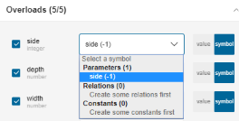
Overload the Parameter
The side value declared at the component level must be overloaded by the side parameter
- Select the FrontWithHandle component and go to the Overloads area.
- Check the box on the left of the
sideparameter. - Move the cursor to Symbol.
- Select the side parameter in the drop-down list.
Test the Opening
Test the opening side of the door front by changing the value of the side parameter to 1.
Handle Replacement
Creating the possibility for the customer to choose between various handles for the same door is a long process that started with a handle parameter in the '"front and handle" sub-assembly.
The action to perform at the top-assembly level is to create a handle parameter and to overload the component value with it.
📌 The final step will be the creation of a product replacement option in the top-assembly datasheet.
Handle Parameter
Start by creating the handle parameter.
- Click Add new parameter.
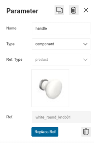
- Click the parameter to access its properties and rename it into handle.
- Select component in the Type drop-down list.
- Click Choose Ref to search for the product using its 3DCloud name, i.e. white_round_knob01 that is the default handle for this cabinet.
- Click the product thumbnail to add it as reference.
Handle Component
Continue by overloading the component.
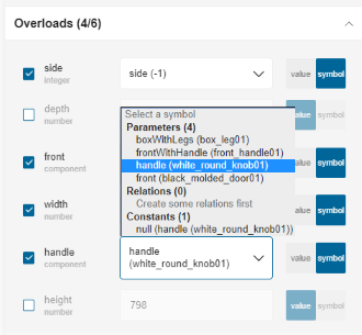
- Go to Components and select FrontWithHandle to access its properties.
- Go to Overloads.
- Select the check box of the handle component.
- Move the cursor to Symbol.
- Select the handle parameter in the drop-down list.
Test the overload by changing the product referenced in the handle parameter.
Save
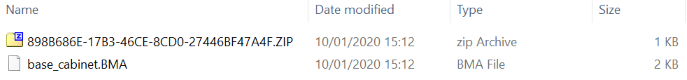
Click the Save my work icon on the up right corner to save the top-assembly as a .BMA file.
Assembly Editor produces a zip file containing a root.BMA file. Move the zip file to your project location and rename the file into base_cabinet.BMA (which will replace the previous one).
The base cabinet is now ready to be displayed in the Kitchen Planner.
Save the Top-Assembly
Click the Save my work icon on the up right corner to save the top-assembly as a .BMA file.
Assembly Editor produces a zip file containing a root.BMA file. Move the zip file to your project location and rename the file into base_cabinet.BMA.