Step 5.b – Create the ‘Front and Handle’ Sub-Assembly
Start from new to create the second sub-assembly.
Add the Components
- Click Create new component on the left menu, or click Add a component on the scene.
- Browse the catalog by specifying the name of the product in the search field. Use either the complete name as defined
in the 3DCloud datasheet or a term of the type e.g. "box" or "front". Press Enter to start
the search.
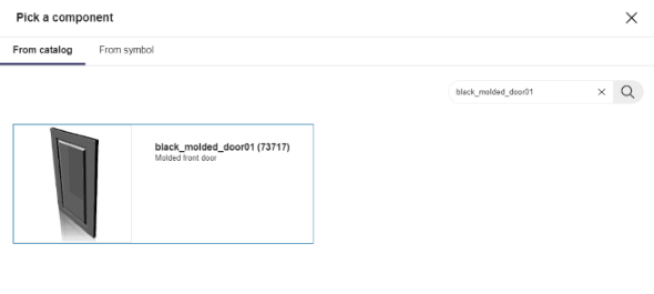
- Click the thumbnail of the product to add it to the list of components and display it on the scene.
- Repeat the proceeding to add the handle (i.e. the white knob). Now you have the following two components.

📌 Remember that the components are centered by default on the origin of the axes. Their final position is not yet defined.
Rename the Components
Select a component in the list or on the scene to display its properties.
Rename the door front component into DoorFront and the knob into Handle.
❗ Always capitalize the first letters of the words in a compound name to avoid confusion with parameter names.

Component Parameters
📌 You create parameters as needed; this is not a batch process with the aim of creating all possible parameters just in case.
Create the Component Parameters
❗ Use camel case convention when renaming the parameters.
You have to create one parameter per component.
To create a parameter, proceed as follows:
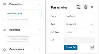
- Click Add new parameter in the Parameters area.
- Click the parameter to display its properties.
- Replace the default name by one matching the naming convention.
- Select component in the Type drop-down list. The associated reference type is specified automatically.
- Changes are saved automatically. Click the cross icon to close the Parameter panel.
🚧 For the "front and handle" sub-assembly of our sample cabinet, create the following parameters:
doorFrontandhandle.
Link the Parameters with the Components
The next step consists in linking each parameter to its component.
- Click the first parameter e.g.
doorFrontto access its properties. - Click Choose ref to select a product reference to link with the parameter.
- Search for the product using its 3DCloud name. Then, click the product thumbnail to add it as reference.
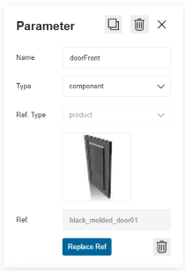
- Repeat the proceeding to link the handle parameter with the handle product and get the following. Note that the component reference has replaced "null" in the parentheses.

Size Parameters and Relations
The next step consists in creating main size parameters identical to the size parameters of the whole cabinet. Relations will refer to these parameters to calculate the real dimensions of the door front dynamically.
❗ These size parameters are mandatory.
Main Size Parameters
- Click Add new parameter in the Parameters area.
- Click the parameter default name to access its properties.
- Rename the parameter into
width. - Select number in the Type drop-down list.
- Enter a value, i.e. 600 for the door front.
- Repeat the proceeding with the height (800) and the depth (600).
The Parameters area now contains the following parameters:

Size Relations
The "front and handle" sub-assembly will use relations to define dynamically some dimensions of the front and the handle.
You have to create a relation to link the width of the door front to the main width parameter while considering its real size (remember that the width of the door front is set to 598 mm in its datasheet).
Start creating the width relation for the front.
- Click Create new relation.
- Click the default name to display the properties of the relation.
- Rename the relation into
frontWidth. - Select Number as type.
- Enter
width –2in the Expression field and press Enter to update the Value field above. The width of the door front is now 598 mm.

Continue by creating the depth relation.
- Click Create new relation.
- Click the default name to display the properties of the relation.
- Rename the relation into
frontDepth. - Select Number as type.
- Specify the Expression field with the following formula, where the dot means to get the value of the depth
parameter for the DoorFront component:
DoorFront.depthand press Enter to update the value.

📌 This type of expression cannot be "undefined" (i.e. ="null"). Do not forget to test the value.
Finally, create a handle size relation.
- Click Create new relation.
- Click the default name to display the properties of the relation.
- Rename the relation into
handleDepth. - Select Number as type.
- Enter an expression relating to the handle component and the depth parameter:
Handle.depthand press Enter to update the value.

Link the Size Parameters to the Door Front
This step consists in defining the size of the component using the size relations.
The front width must vary while stretching the cabinet; front depth is defined dynamically for the case when the customer changes the door with one thicker or thinner, to ensure that the handle remains well placed.
- Click the DoorFront component in the list to access its properties.
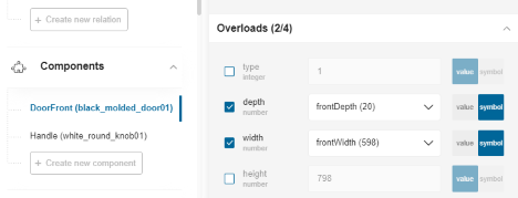
- Scroll down to the Overloads field. The size parameters displayed in this area are recovered from the 3DCloud datasheet.
- Select the check box regarding the width of the component to enable the modifications.
- Move the cursor to Symbol to display the list of parameters declared in Assembly.
- Select the
frontWidthrelation. - Select the depth check box, move the cursor to Symbol and select the
frontDepthrelation.
Those calculated via the relation now overload the width and depth of the "DoorFront" component.
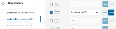
Repeat the proceeding with the depth of the handle. Select the Handle component and link it to the handleDepth
relation.
Front Position
By default, the door is placed on the scene at the origin point like any component. Now we will place it on the front of the box.
Create Position Relations
The position of the front on the Z-axis must be calculated dynamically to follow the stretching of the whole cabinet.
- Click Create new relation.
- Click the default name to display the properties of the relation.
- Rename the relation into
yFrontPosition. - Select Number as type.
- Enter
-depth*0.5 - frontDepth*0.5in the Expression field. The formula is based on the half of the main depth and the half of the front depth. - Press Enter to update the Value field above. The value is now -310.

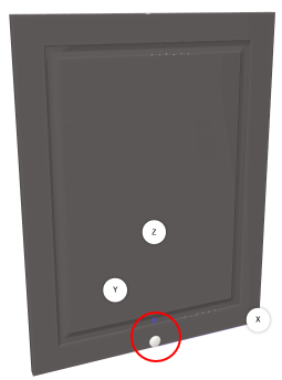
Door Front Position
The final step consists in overloading the position of the door front component with the front position relation.
- Click the DoorFront component to access its properties.
- Go to Position and move the cursor to Symbol for the Y position.
- Select yFrontPosition in the list of relations.
The door is now placed as illustrated below. Note that the handle is still on the default position.
| Bottom view | Side view |
|---|---|
 | 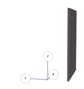 |
Opening Side Parameter
The next step for this sub-assembly is to define a side parameter, as in the 3DCloud datasheet, to specify the opening side of the combination door front and handle.
🚧 This parameter is in relation with the future animation of the base cabinet: opening the door.
- Click Add new parameter and click the default name to access the properties.
- Rename it into
side. - Select number (or integer ) in the drop-down list.
- Enter -1 in the Value field because the door front is left opening (1 for a right opening door).
- Press Enter to validate the parameter.
📌 To be valid, the side parameter must be used in two relations: the x-position of the handle and the rotation axis. See hereinafter.
Handle Position
The position of the handle must remain constant even if the door is stretched horizontally. The relation will be calculated from the main size parameters and offsets to specify the position from the edge of the front.
🚧 For our sample cabinet we will use an offset of 160 mm from the top and side edges of the door to place the knob.
Create Position Relations
Start by creating the position on the X-axis.
Note that this relation will use the side parameter that we have just created.
- Click Create new relation.
- Click the default name to display the properties of the relation.
- Rename the relation into xHandlePosition.
- Select Number as type.
- Enter
(width*0.5 - 160)*-sidein the Expression field. - Press Enter to update the Value field.

Continue by creating the position on the Y -axis. The formula is based on the depth parameter, the depth of the front and the depth of the handle.
- Click Create new relation.
- Click the default name to display the properties of the relation.
- Rename the relation into
yHandlePosition. - Select Number as type.
- Enter
-depth*0.5 - frontDepth - handleDepth*0.5in the Expression field. - Press Enter to update the Value field.

Finally, create the position on the Z-axis. The formula calculates the position from the main height parameter, the height from the floor (the legs actually) and the offset.
- Click Create new relation.
- Click the default name to display the properties of the relation.
- Rename the relation into
zHandlePosition. - Select Number as type.
- Enter
height + 80 -160in the Expression field (where 80 is the height from the floor and 160 is the offset of the handle from the edge of the door front). - Press Enter to update the Value field.

Handle Position
Now that the position relations are defined, you have to overload the position of the handle with these relations.
- Click the Handle component to access its properties.
- Go to Position and move the cursor to Symbol for the X position.
- Select xHandlePosition in the list of relations.
- Overload the Y value with yHandlePosition and the Z value with zHandlePosition.
The handle is now placed as illustrated below:
| Bottom view | Side view |
|---|---|
 | 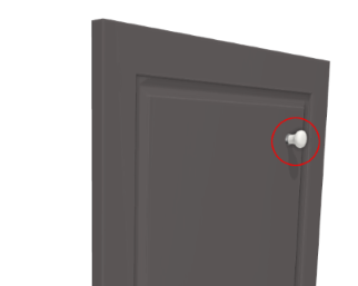 |
Add an Animation
Animations make it possible to define kinematic behaviors in the Kitchen Planner, such as opening the door of the base cabinet.
Animations – either a rotation or a translation – apply to the components of an assembly as a whole. Thus, do not create the door animation at the top-assembly level because it would not be possible to rotate only the door front component within the whole assembly. Create the door front animation on the "front and handle" sub-assembly.
The animation of opening a door is a rotation: the door front will rotate on the Z-axis. A translation would consist for example in opening a drawer from a cabinet on the Y-axis.
Create a Relation
To give the customer the possibility to change the direction of the door opening in the Kitchen Planner, you have to define the position of the rotation axis dynamically.
- Click Create new relation.
- Select the default name to access its properties and rename it into
xRotationAxisPosition. - Enter the following formula in the Expression field, using the side and width parameters:
side*width*0.5. - Press Enter to update the value.

Create the Rotation
Scroll down the left menu to Animation and click Add a rotation.

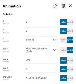
- Click the rotation to display its properties.
- Specify the direction of the rotation: move the cursor to Symbol for the Z field and select the side parameter in the list.
- Specify the position of the rotation axis: a. Select Symbol for the axis x field and then, xRotationAxisPosition. b. Enter -300 (which is the half of the box depth) in the axis y field to place the rotation axis on the front. c. Leave the axis z blank.
- Keep the default value in the endAngle field.
Test the Animation
Test the animation by clicking the Play icon either on the left menu or on the property panel.
Also test the possibility of a right opening door by changing the value of the side parameter to 1 and clicking the Play icon.
| Edit menu | Property panel |
|---|---|
 |  |
Save the Front and Handle Sub-Assembly
Following the data model (see above Data Model) the door front and the handle must be saved as a sub-assembly. This is recommend to make it reusable and necessary if you want to add an animation that will open the door front (handle and door front must work as a group).
Save the Work
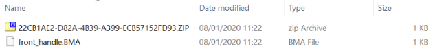
Click the Save my work icon on the up right corner to save the sub-assembly as a .BMA file. Assembly Editor produces a zip file containing a root.BMA file. Move the zip file to your project location and rename the file into front_handle.BMA.
Create a Datasheet
Then, create a product datasheet in 3DCloud for this sub-assembly. Import the .BMA file as 3D Model representation.
You have to define in the 3DCloud datasheet all the parameters that are defined in Assembly.
Click Create parameter to add the size parameters of the door front.
Add a product parameter to create a choice of handles in the Kitchen Planner.
Finally, add the new product to the catalog.
Whereby, you will be able to import it as a component in Assembly Editor to continue building the base cabinet.