Feature details
Please note that the Assembly fundamentals are described in Product and Assembly reference
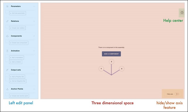
Interface Overview
Top Bar
![]()
![]() : Create a new assembly
: Create a new assembly
![]() : Open from a local file
: Open from a local file
![]() : Open from a URL
: Open from a URL
![]() : Save the assembly file locally
: Save the assembly file locally
Central User Interface
Assembly Parameters
-
Declaration, copy, deletion

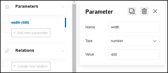
To declare a new parameter, click "Add new parameter" on the left side panel. The parameter is set with a default name "NewParameter0" (the last number is incremented if the parameter name already exists).


To edit the parameter, click the parameter name: an edit panel appears on the right side with three different entries: name, type and value.
To duplicate the parameter, click
 . The new parameter is a copy of the parameter duplicated (same type and same
value). Its name is ending with "-copy0" (the last number is also incremented on the same model described above).
. The new parameter is a copy of the parameter duplicated (same type and same
value). Its name is ending with "-copy0" (the last number is also incremented on the same model described above).

To delete the parameter, click .
. -
Name
The assembly parameter name should be:
- Following the guidelines
- Identical to the corresponding product parameter name, in order to create a binding
- Different from any relation name
-
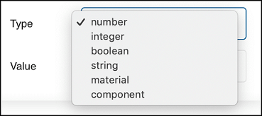
Type
The parameter type is chosen in the list:
-
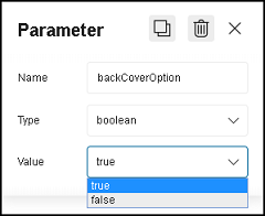
Value
The user declares the default value of the parameter. This value is used to instantiate the product in Assembly Editor, and is kept at runtime if no external setting happens.
The UI used to set the value is dependent on the type:


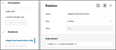
Relations
-
Creation
To create a new relation, click "Create a new relation" on the left side panel. As for parameters, the relation created is set with a default name "NewRelation0" (the last number is incremented if the relation name already exists).


To edit the relation, click the relation name: an edit panel appears on the right with three different entries: name, type and expression. There is also a library that can be shown or hidden.
To duplicate the relation, click ![]() . The new relation is a copy of the relation
duplicated (same type and same expression). Its name is ending with "-copy0" (the last number is also incremented on the
same model).
. The new relation is a copy of the relation
duplicated (same type and same expression). Its name is ending with "-copy0" (the last number is also incremented on the
same model).
To delete the relation, click ![]() .
.
Finally, the expression editor gives useful information about the validity of the expression written (unknown
identifier, wrong syntax, etc.).

- Library Panel
The library panel makes it easy to navigate within the input terms that can be used in expressions.
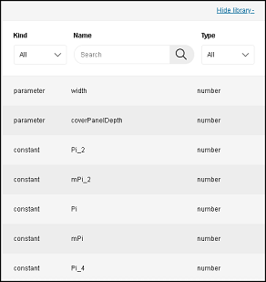
The panel contains:
- constant values (such as PI and PI factors for trigonometric operations),
- parameters from the current assembly
- relations from the current assembly
- components from the current assembly
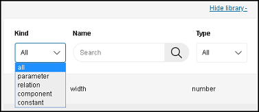
To easily find what is needed, the user can filter as per:
"Kind": [parameter; relation; component; constant]
"Name": search field
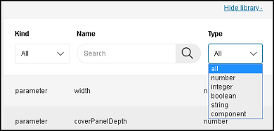
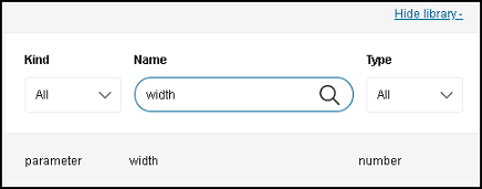
"Type": [number; integer; boolean; string; component]
Components
-
Adding a component to an assembly
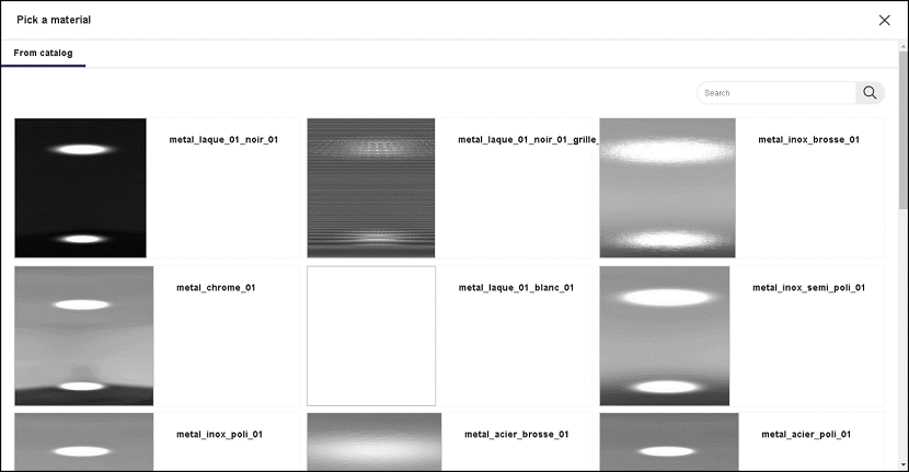
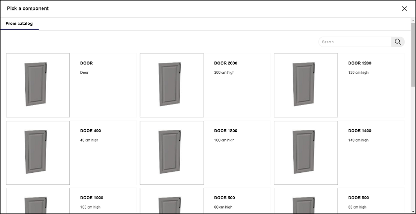
To declare a component, click "Create new component". The "Pick a component" panel frame appears at the center of the screen. The user can search and select products:- "From catalog": The search feature fetches products from the XXX product catalogs that are linked to the Assembly
Editor through the application distribution used.
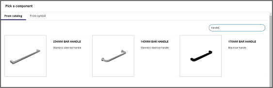
- "From symbol": It fetches products from parameter and relation values already created in the current assembly, if
any.
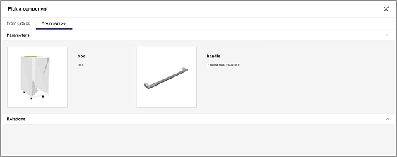
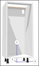
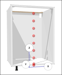
Once the user has selected the desired product, the 3D model (if present), appears in the viewer. The component name is set by default to: "NewComponent0" (the last number is incremented if the component name already exists).
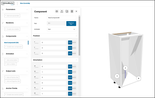
The default position of the 3D model is centered on the "x" and "y" axis. For the "z" axis, the lowest 3D model triangle appears on z = 0.
These conventions are relied upon in the applications (for floor positioning, furniture rotation...) so it is best to keep this position.
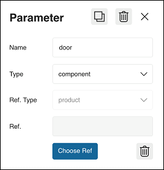
To edit the component, click the component name: an edit panel appears on the right showing the component properties, with its default values.
To show/hide the 3D model, click:
 (the component is visible),
click to hide it, (the component is hidden, click to show it).
To open the component assembly, click
 .
.To duplicate the component, click
. The new component is a copy of the
component duplicated (same properties). Its name is ending with "-copy0" (the last number is also incremented on the
same model).To delete the component, click
. - "From catalog": The search feature fetches products from the XXX product catalogs that are linked to the Assembly
Editor through the application distribution used.
-
Naming guidelines
Same guideline as for the parameters except that we would advise to use the Pascal camel-case (or upper camel-case) convention to differentiate them from parameters and relations that could have the same name.
example: BoxAssembly, Handle, Front, Door,... etc. -
Component properties
-
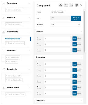
The top bar of the "Component" edit panel shows again the different actions the user can operate and that were already described above.

-
Name: name of the component, it is advised to change the default one using the guideline described above in the " naming guidelines" section.

-
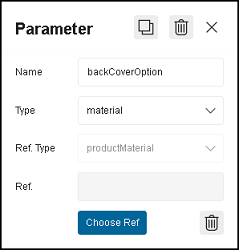
Ref.: product reference of the database used in the current component. The user can replace the reference by clicking on "Replace.
Ref.": the "Pick a component" panel frame appears back to make the replacement (with same options "From catalog" or "From symbol").
For more information, refer to the component "Definition" section above.
If a product from the catalog is selected, only the name of the product appears in the reference field:

If a parameter/relation from the symbols is selected, the parameter name with its value in brackets in displayed.

-
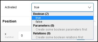
The "activation/deactivation" feature: It is a boolean property. If true, the component is activated, if false, the component is deactivated.
The feature is different from the "show/hide" feature described above because "show/hide" is only about displaying in the current session of Assembly Editor viewer whereas "activation/deactivation" is activating/deactivating the component so that it appears or not in the planner.Also, if deactivated, the pricing calculation is not taking the component into account.
The "Activated" field is a dropdown list with the boolean two state values "true" and "false" and also the different boolean parameters and/or relations that were previously created by the user in the current assembly, which makes it possible to implement parametric component inclusion.
-
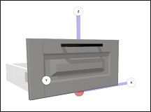
Position and Orientation: The 3D space defined by the viewer is a orthonormal coordinate system. The user can define the position of any components by giving the coordinates (in millimeter) on the 3 axes: x, y and z. By convention, the x axis defines the left-to-right axis, the y axis defines the front-to-back axis and the z axis defines the bottom-to-top axis.

The orientation of the component can also be set by changing the values of yx, yy, yz, zx,zy and zz. Those fields correspond to the oriented vectors Y'(yx, yy, yz) and Z'(zx, zy, zz) that define the orientation between the component coordinate system and the current assembly coordinate system.
For both position and orientation, the user can either:
- enter a fixed value (toggle button is on the "value" side): the value type has to be a number.
- select a symbol (toggle button is on "symbol" side): the drop down list shows only the parameters and/or relation that are numbers. By doing so, the user makes the orientation and/or orientation of the component * parametric*.
-
Overloads: an overload is the concept of taking control over a component parameter by binding it to a parameter or a relation of the current assembly. The "Overload" section shows the user the entire list of the component parameters.
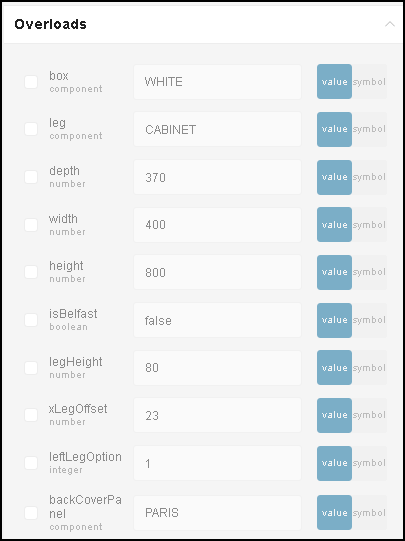
To activate an overload, the user has to check the box.

When checked, the parameter is unlocked for overload. The user can either:
- enter a fixed value (toggle button is on the "value" side): the value type has to be the same as the parameter type (if the parameter is a boolean, either true or false has to be entered, if the parameter is a number, a numerical value has to be entered,...etc).
- select a symbol (toggle button is on "symbol" side): the drop down list shows only the parameters and/or
relation that are the same type as the parameter the user is overloading.

When the overload is made through a symbol, the field shows the symbol name with its value in brackets.

-
Animations
-
Definition
Animations make it possible to define kinematic behaviors in the ByMe planner, such as cabinet door opening.
Animations - either a rotation or a translation - are defined in Assembly Editor.
The scope of the defined animation is the whole assembly - not subcomponents.
To edit the animation, click the "translation" or "rotation" created.

Once a translation (or a rotation) is created, the "Add a rotation" button (or "Add a translation") switches to " Replace with a rotation" (or "Replace with a translation").


To play the animation, click
 .
.
To delete the animation, click. -
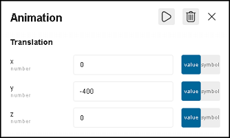
Translation
Translation animation is defined by a vector coordinates in the x, y and z axis. Coordinates are set in millimeters. As for position, orientation and overload, the user can either put a fixed value (number) or a symbol ( parameter/relation) thanks to the toggle button "value/symbol".
-
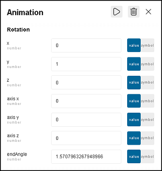
Rotation
Rotation animation is defined by a rotation axis (position and direction), and the value of the maximal angle excursion. The rotation vector is defined by the x, y and z fields, axis position is defined by the axis x, axis y and axis z fields, and angle end value is defined by the endAngle field.
Output Sets
-
Definition
In Assembly Editor, an output set is a linear information that the Range Manager needs to add in specific cases to handle application features requiring 2D as input.example: in the kitchen application, output sets are used to define the 2D properties of plinth, worktop, wall panels, decostrip and cornices paths.
-
Creation
Output set can either be a polyline set (allow only lines defined by points) or an edgeline set (allow lines and circles defined by points and radiuses).To create a polyline set (or an edgeline set), click "Add a Polyline Set" (or "Add an Edgeline Set"). The polyline set (or edgeline set) created is set with a default name "NewOutputSet0" (the last number is incremented if the output set name already exists). The type of output set (polylines or polyedges) is written in brackets after the output set name. To edit the output set name, click the output set line created on the left panel.
The name is mandated by the expected feature. For example, put the name "worktopCut" to define a cut-out for a worktop or "section" to define a plinth cross-section. Please refer to the application documentation for the full list of names.

To duplicate the output set, click ![]() . The new output set is a copy of the output
set duplicated (same properties). Its name is ending with "-copy0" (the last number is also incremented on the same
model).
. The new output set is a copy of the output
set duplicated (same properties). Its name is ending with "-copy0" (the last number is also incremented on the same
model).
To delete the output set, click ![]() .
.
-
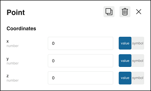
Creating a Polyline
As polyline is defined by a set of points (at least two).
To create a polyline, click "Add a Polyline".

To create a point, click "Add a Point".

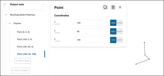
To edit a point, click the point created. An edit panel appears at the right side. The user can then edit the
coordinates of the point (x, y and z). Again, the user can either enter a fixed value or use a parameter/relation of the
current assembly (type number) by using the toggle button "value/symbol".

By creating the different point, the user is able to see the result directly in the space on the right part of the
screen.
To duplicate a point or an entire polyline, click ![]() . Contrary to
parameters/relations and components, the user can not edit the name: the polyline name (or the point name) is set to
be "Polyline" (or "Point).
. Contrary to
parameters/relations and components, the user can not edit the name: the polyline name (or the point name) is set to
be "Polyline" (or "Point).
To delete a point or an entire polyline, click ![]() in regard of the item to delete.
in regard of the item to delete.
-
Creation of a Polyedge
A polyedge is defined by one edge line and/or one edge circle (at least one of them).
The user can either create a line by clicking on "Add a line Polyedge" or a circle (or circular arc) by clicking on " Add a circle Polyedge".

An edge line is defined by a start point and an end point (x and y coordinates).
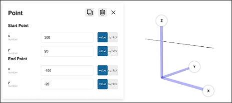
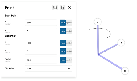
An edge circle is defined by a start point and an end point (x and y coordinates), by a radius and a direction ( clockwise or anticlockwise).
To choose the clockwise direction, the clockwise value has to be "true".
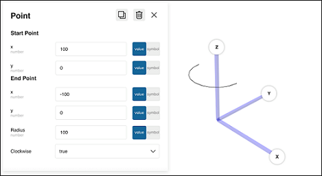
For the anticlockwise direction, clockwise value has to be "false".
As for the point coordinates in the polyline case, the user can either use fixed numerical values, or parameters/relations (toggle button).
To duplicate an line edge (or a circle edge), click
. As for the polyline,
the user can not edit the name: the line edge (or the circle edge) is set to be "EdgeLine" (or "EdgeCircle").To delete an item, click
in regard of the item to delete.
Anchor Points
-
Definition
Anchor points are used to define the different possible positions of an assembly component in relation to another component. One usage scenario of this data is in cabinet configurator, where anchor points put constraints on where an end user can position subcomponents.Click here for more information on cabinet configurator.
The cabinet configurator lets the user compose its own furniture by placing its chosen components, the "target"
components, in relation to another unique component, the "receive" component.
To do so, the Range Manager has to create anchor points in a way that a mapping is done between the "target" anchor
points and the "receive" anchor points.
The mapping is done through the concept of "tags" which is described under in the "properties" section.
To create an anchor point, click "Create new anchor point".

To edit the anchor point created, click the line created on the left panel: a edit panel appears on the right side.

To duplicate the anchor point, click ![]() .
.
To delete the anchor point, click ![]() .
.
- Properties
An anchor point is defined by its position, its orientation and its tags (at least one).

"Type" field is locked to "AnchorPoint" and can not be changed by the user. The "Tags" field is a free string field
where the user can write all the different tags chosen (no constraints on the tag names). Those tags represent the "
target" tags.
To add a tag, just write it in the corresponding field and press enter.

![]()
To create several tags, repeat the same operation.
![]()
To delete a tag, click ![]()
Position and orientation works the same as a component (refer to "component" section).
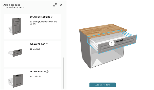
Available Space
The available space is the value to which the guest component (i.e. Doors, Drawers, Cabinet shelves, or Fronts) is
resized when modifying the cabinet inside the Cabinet Editor. The guest component is resized if the available space is a
valid value (i.e. non zero positive value) & is compatible with the possible depth/width parameter of the guest
component.
By default, the resized value for the width/ depth is the width/ depth of the receiving component (i.e. Box Assembly).
See Resize a guest component for
more details about resizing the guest component in cabinet editor.
You can define available space for width & depth by setting x & y values respectively in the Available Space section
of the anchor point.

For available space, the user can either:
- Enter a fixed value: Activate the Value button & add the value. The value should be a number.
- Select a Symbol: Activate the Symbol button & Select the relation or parameter from the drop-down list.
Receive Tags
To create a receive tag, click "Add a receive tag" at the bottom of the panel.

A "Tags" field appears that works exactly the same as the "target" tags field (the one at the top of the edit panel).

The rotation of the component can only be set by changing the values of YX, YY, YZ, ZX, ZY and ZZ axis in the Orientation section of Anchor Point.