Assemblies
Fundamentals
Components
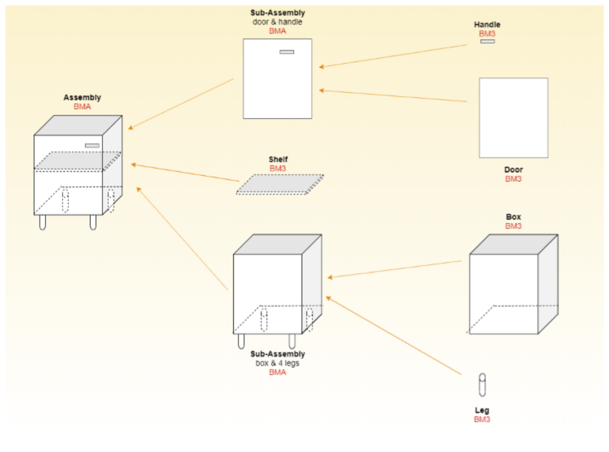
An Assembly is a collection of Components. The assembly manages several aspects of the relationship between itself and its components, noticeably:
- The Assembly’s geometry is the geometric combination of all its Components, taking into account their position ( translation and rotation), and optional kinematics,
- The Assembly’s price is the sum of the price of components,
- The Assembly orchestrates the valuation of parameters.
Components are instances of either
- Products with a final geometry, represented by BM3 resources (“leaves”),
- Assemblies represented by BMA resources (“sub-assemblies”),
- In some modelling edge cases, the designer might model some assembly components without geometries.
Designing complex products as assemblies (opposed to monolithic BM3 resources) brings several advantages :
- Reuse of subcomponents across several assemblies ;
- Configurability of the product, cascading to components ;
- Pricing automatically computed as the sum of parts.
Assemblies are created and modified in Assembly Editor. Please refer to the Assembly Editor documentation 🔗 for reference.
Instances and References
The Components of the Assembly are instances referencing ByMe Products (by their ID).
An instance has the following attributes:
- Product reference (Product ID),
- Relative position (x, y z) and orientation (yx, yy, yz, zx, zy, zz) - see below,
- Activation status (boolean),
- Parameter overloads (see below).
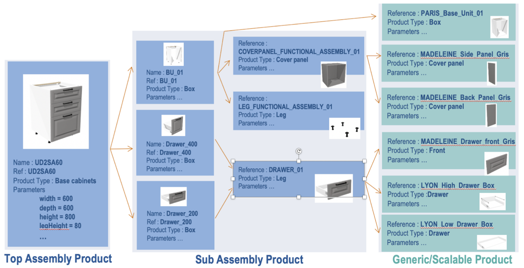
This diagram exemplifies the difference between instance and reference : the 4 legs of this assembly are 4 different instances of the same reference. These different instances have different positions, and possibly orientations.
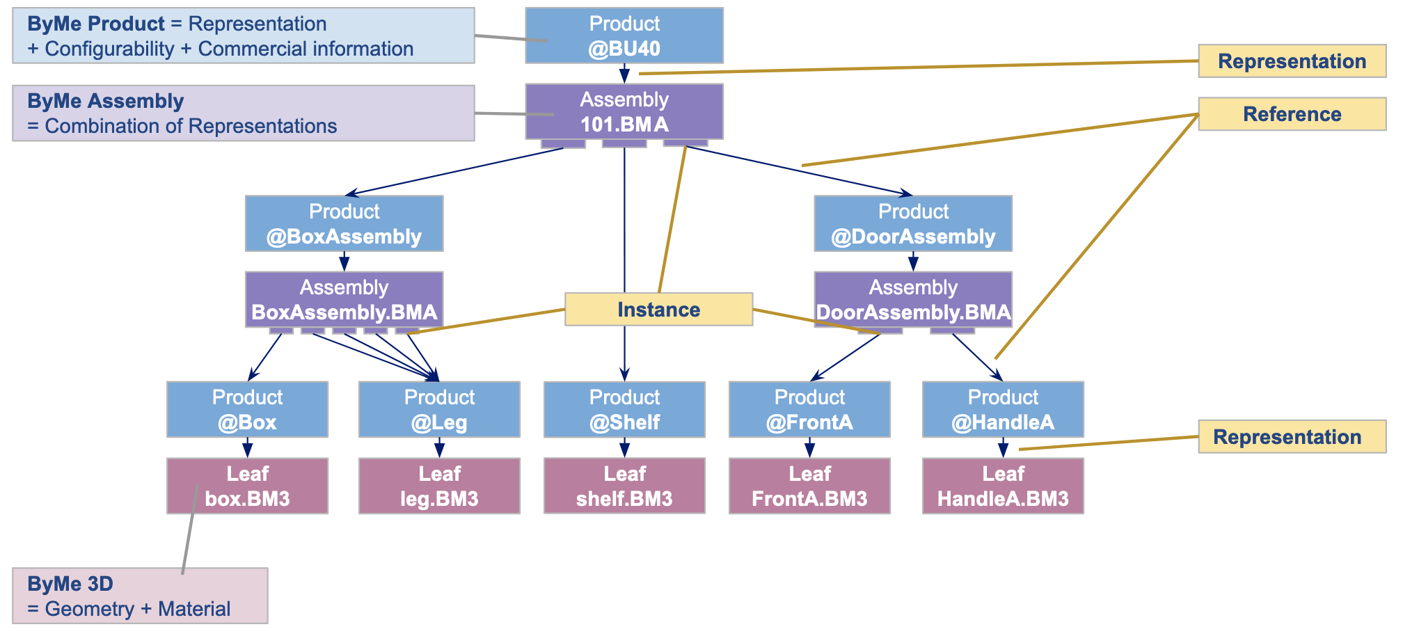
The result is a tree called Product Structure:
- Whose nodes are BMA components
- Whose leaves are BM3 components
- Whose branches are instances
- Whose root is a node and a commercial product,
Orientation, rotation
This section describes how to setup the (yx, yy, yz, zx, zy, zz) instance attributes to define the component orientation relative to its parent.
Component scaling is not managed through a transformation matrix, but instead by overload of width, depth, height parameters.
Cheat sheet
| Attribute | yx | yy | yz | zx | zy | zz |
|---|---|---|---|---|---|---|
| Identity (no rotation) | 0 | 1 | 0 | 0 | 0 | 1 |
| Θ around X axis | 0 | cos θ | sin θ | 0 | -sin θ | cos θ |
| 90° around X axis | 0 | 0 | 1 | 0 | -1 | 0 |
| -90° around X axis | 0 | 0 | -1 | 0 | 1 | 0 |
| Θ around Y axis | 0 | 1 | 0 | sin θ | 0 | cos θ |
| 90° around Y axis | 0 | 1 | 0 | 1 | 0 | 0 |
| -90° around Y axis | 0 | 1 | 0 | -1 | 0 | 0 |
| Θ around Z axis | -sin θ | cos θ | 0 | 0 | 0 | 1 |
| 90° around Z axis | -1 | 0 | 0 | 0 | 0 | 1 |
| -90° around Z axis | 1 | 0 | 0 | 0 | 0 | 1 |
General case We refer to the standard expression of the rotation matrix:
| xx | yx | zx |
| xy | yy | zy |
| xz | yz | zz |
The (yx, yy, yz, zx, zy, zz) values are the coordinates of the component axes Y (yx, yy, yz), Z (zx, zy, zz) in the assembly axes.
X(xx, xy, xz) does not need to be provided as it is implied by X, Y, Z being a orthonormal, direct axis system.
The provided (yx, yy, yz, zx, zy, zz) values must enforce the following constraints:
- || Y || = sqrt (yx^2 + yy^2 + yz^2) = 1 (no scaling)
- || Z || = sqrt (zx^2 + zy^2 + zz^2) = 1 (no scaling)
- Y.Z = yx.zx + yy.zy + yz+zz = 0 (orthogonality)
The general formula for a combination of yaw, pitch and roll is the following :
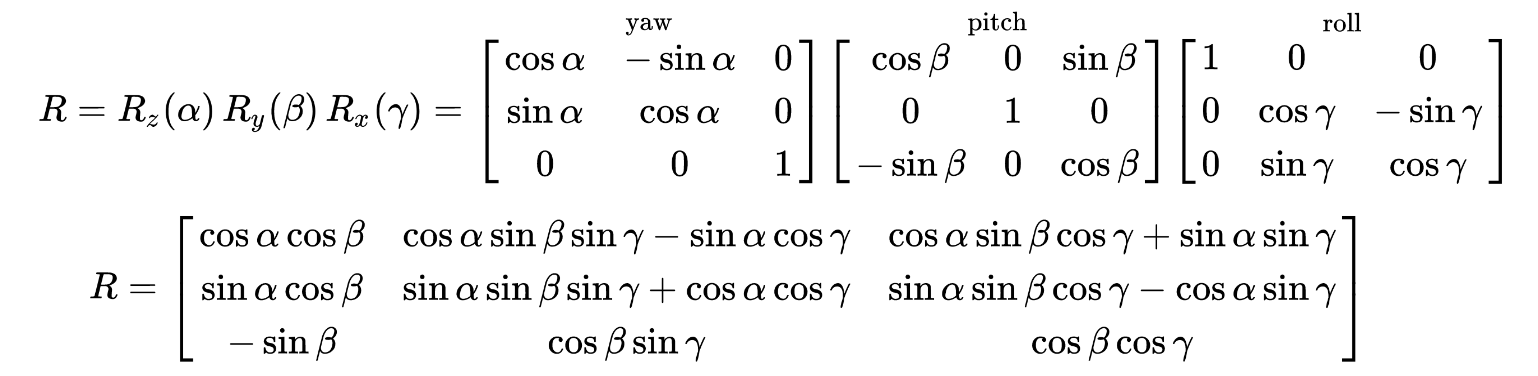
Background: https://en.wikipedia.org/wiki/Rotation_matrix 🔗
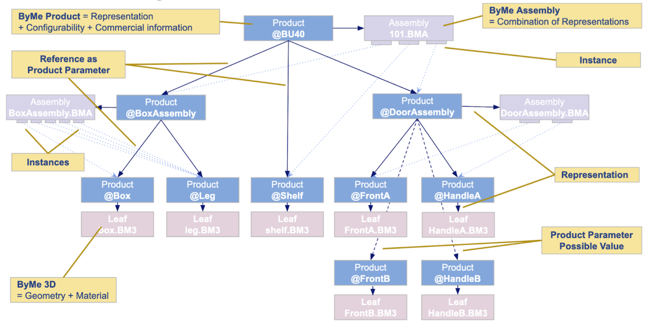
Parametric Product Structure
The recommended design of a ByMe Product Structure is parametric.
This means that the reference link between an instance within an assembly (eg. BoxAssembly.BMA), and the product representing this component (eg. @Box) should not be stored as a fixed reference in the BMA, but should instead be represented as a parameter of the @BoxAssembly product.
When this convention is used, the conceptual diagram of the Product Structure has direct Product-Product reference
links. This chapter details how this design can be achieved.
Assembly parameters
An Assembly declares a list of parameters representing its “degrees of freedom”. The structure is slightly different from Product Parameters. Each parameter declares
- A name - same guidelines as Product Parameter names,
- A type - same types as Product Parameters,
- A value, which is the default value when the Assembly is considered outside of the scope of a Product (eg in Assembly Editor), or that the Product does not set its value. The parameter can take any value - unlike Product Parameters which have a defined set of possible values.
Automatic Binding of Product Parameters to Assembly Parameters
When an Assembly is used as the representation of a Product, there is an automatic, unidirectional binding of parameter values from the Product to the Assembly.
Example :
| Parameter | Value in Product declaration | Value in Assembly declaration | Initial runtime value in Assembly |
|---|---|---|---|
| width | 600 | 400 | 600 |
| depth | 600 | 580 | 600 |
| height | 787 | 800 | 787 |
| finish | Matte | Not declared | - |
| drawerGap | Not declared | 3 | 3* |
- Please note that we recommend against setting constants in resources. As any developer knows, constants change, hence they should be exposed as Product Parameters. This is especially useful to make BMA resources reusable across products now and in the future.
Assembly relations
Definition
In an assembly, relations are expressions used to compute dynamic values.
These expressions can use the following inputs :
- Assembly parameter values
- Parameter values of sub-components
- Other relations
- Any number and any standard JS operator
Relations CANNOT use the following inputs:
- Parameter values of parent components
- Sub-component references
The result of the evaluation of the expression can be assigned to :
- Instance attributes (placement, orientation, activation, but NOT reference, which should be set directly by an Assembly parameter value, binded to a Product parameter),
- Output set properties,
- Anchor points properties,
- BUT NOT to the attributes or parameters of the containing Product.
Naming guidelines
Same guidelines as for the parameters.
Type
Supported types for expression result are : number, integer, string, boolean.
Available symbols
Expressions reference available symbols as inputs:
- Current Assembly parameters : xLeftLegOffset
- Current Assembly relation results : calcThick - only for for previously declared relations,
- Component parameter value : Component.parameter
- example : the expression “Front.depth” fetches the “depth” parameter value of the component named “Front” in the assembly.
- Constants :
- Numerals : 2, 600, 0.5…
- Predefined values : Pi, mPi (=-π), Pi_2 (=π/2), mPi_2 (=-π/2), Pi_4 (=π/4)
- Real-world constants, such as mentioning 18 for wood thickness, are generally discouraged since they tend to prevent reuse and resilience to change. As in software, constants should be externalized, exposed as parameter default values which can be overloaded, or top-level parameters.
⚠️ When using a component parameter value, always test the value of the corresponding parameter (with a ternary
operator typically). For example, if there is a parameter "handle" and an associated component "Handle", here is how to
access Handle.depth: “handle !== null ? Handle.depth : 0”.
If you do not do that:
- the relation can crash if handle is set to null, which can happen depending on the catalog
- there is no explicit default value
- the relation will not update its value automatically when the component reference changes
Expression operations reference
Unary operators
| Operator | Comment |
|---|---|
| - | The unary negation operator converts its operand to Number type and then negates it |
| ! | Logical NOT operator, for booleans |
Arithmetic operators
Arithmetic operators take numerical values (either literals or variables) as their operands and return a single numerical value.
| Operator | Comment |
|---|---|
| + | Addition operator |
| - | Subtraction operator |
| / | Division operator |
| * | Multiplication operator |
| % | Remainder operator |
Relational operators
A comparison operator compares its operands and returns a Boolean value based on whether the comparison is true.
| Operator | Comment |
|---|---|
| < | Less than operator |
| > | Greater than operator |
| <= | Less than or equal operator |
| >= | Greater than or equal operator |
Equality operators
The result of evaluating an equality operator is always of type Boolean based on whether the comparison is true.
| Operator | Comment |
|---|---|
| === | Identity operator for product references, Equality operator for numbers, strings and booleans (without auto coercition, avoiding unforeseen implicits) |
| !== | Nonidentity operator for product references. Inequality operator for numbers, strings and booleans (without auto coercition, avoiding unforeseen implicits) |
Binary logical operators
Logical operators are typically used with boolean (logical) values, and when they are, they return a boolean value.
| Operator | Comment |
|---|---|
| && | Logical AND |
| || | Logical OR |
Conditional (ternary) operator
| Operator | Comment |
|---|---|
| (condition ? valueIfTrue : valueIfFalse) | The conditional operator returns one of two values based on the logical value of the condition |
Math Operators
The ByMe expression language is based on the Math Javascript Library : https://developer.mozilla.org/en-US/docs/Web/JavaScript/Reference/Global_Objects/Math The functions typically used in the ByMe context are:
| Operator | Comment |
|---|---|
| Math.sin(x) | Returns the sine of x |
| Math.cos(x) | Returns the cosine of x |
| Math.abs(x) | Returns the absolute value of x |
| Math.floor(x) | Returns the largest integer less than or equal to x |
Expressions examples
- simple operations, such as addition, subtraction, multiplication, division, … etc.
- example : (width / 2) + xLeftLegOffset.
- math operations, by using the “Math” javaScript global Object.
- example : -Math.cos(angleRad-Pi_2).
- ternary expressions,
- example n°1 : (width > 600) ? true : false
- example n°2 : (handlePosition == 0) ? handleOffset : height - handleOffset.
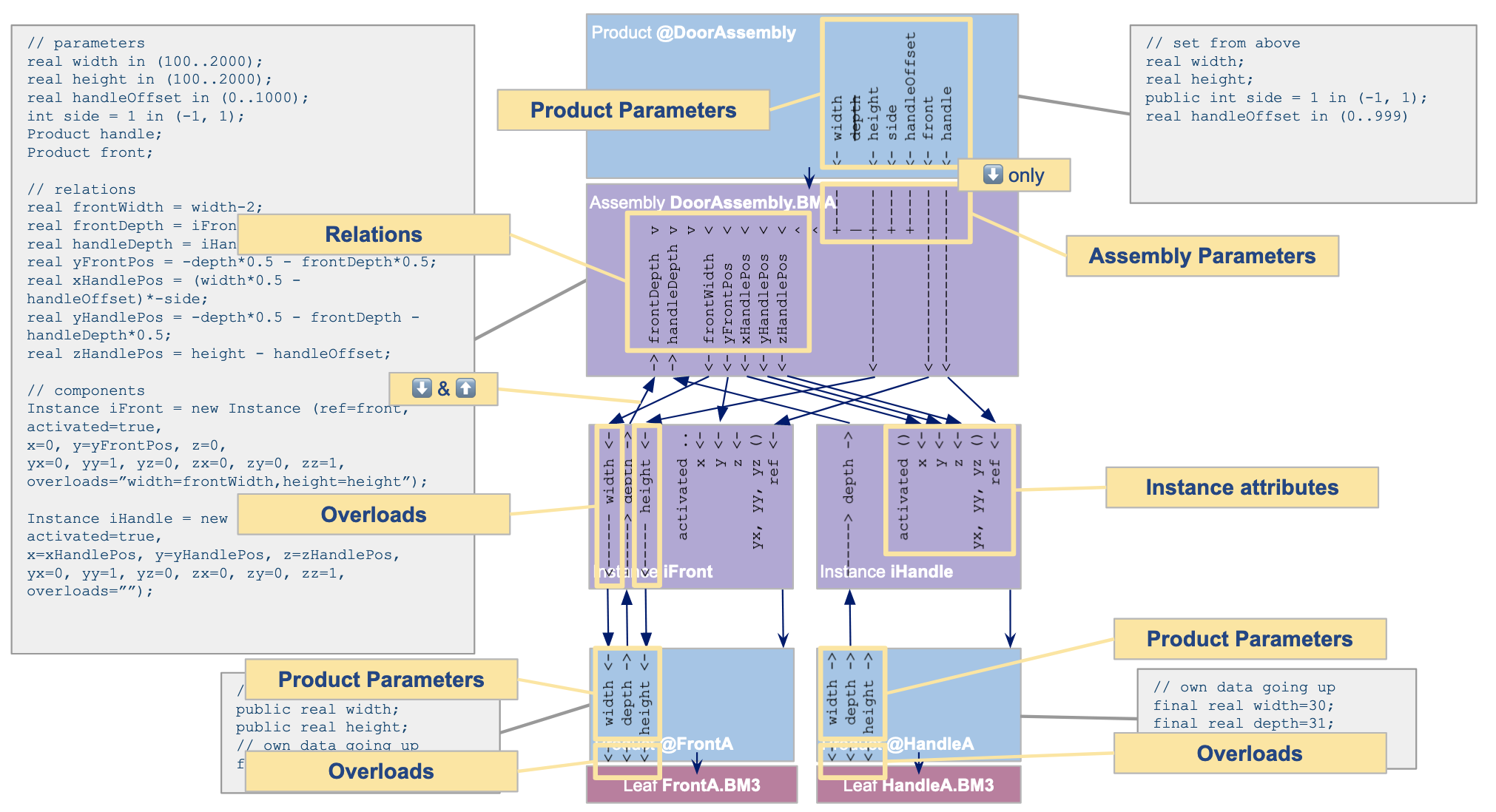
Parametric Instances, Overloads
Assembly Parameters and Relations’ significant role in parametric product structures originates from the ability for Assembly Instances to reference them, which, coupled with Product->Assembly parameter binding, makes it possible to * cascade values and behaviors top-down in the Product Structure*.
Component Instance valuation:
| Instance Attribute | Possible origination |
|---|---|
| name | fixed value |
| reference | fixed value(1), or Assembly parameter |
| activated | fixed value, Assembly parameter or Assembly relation |
| x, y, z | fixed values, Assembly parameters or Assembly relation |
| yx, yy, yz, zx, zy, zz | fixed values, Assembly parameters or Assembly relations |
| overloads | no overload, fixed values, Assembly parameters or Assembly relations |
(1) Not recommended
Downwards vs. upwards
Overloads, as declared in the Assembly instance, allow setting a Component Parameter from an Assembly Parameter, or relation (“downwards”).
Assembly relations allow to reference the value of a component parameter in an Assembly (“upwards”).
This is a modelling choice depending on the desired effect. Obviously a given component parameter can not be referenced both ways. This would produce unpredictable results.
Schoolcase : Configurable Assemblies and Parametric Product Structure
In this end-to-end schoolcase we illustrate the Parametric Assembly fundamentals:
- Product and Product Representation
- Product Structure
- Product Parameter,
- Assembly Parameter and binding
- Assembly Relations
- Assembly Instances, Instance attributes, References,
- Overloads
The complete step by step tutorial to create this schoolcase can be found here.
Summary : Parametric Assembly design patterns
| Resource Instanciation | A Product setting parameter values on its geometric representation (BMA or BM3 resource) reducing its “degrees of freedom”. In some cases Range Managers use existing resource libraries, whose documentation specify the expected parameters. |
| Smart assembly | A BMA leveraging parameter values from its enclosing product, its components, and implementing geometry and behaviors through relations |
| User configurability | A Product describing the configurability space and binding it to its representation |
| Component properties | Components, especially leaves of the product structure such as door handles, expose Product Parameters, such as dimensions or type, which are used in enclosing assemblies relations for component placement. Examples: Handle width, handle type |
| Application parameters | Some ByMe applications, like HomeByMe for Kitchen Retailers, make sense of the value of some Product parameters. These parameters are not used in the geometric representation (and thus not binded to the BMA/BM3 resource). Examples: - Commercial description displayed in the Product panel , - Commercial width used as a catalog filter , - Plinth option, edge compatibility , triggering Kitchen behaviors. The full specification of such application parameters can be found the documentation of each application. |
More BMA files fundamentals
Anchor points
Anchor points are defined by Range Managers within assemblies, so that end-users can use Cabinet Editor to move and replace components within the assembly within defined contraints.
This scenario is described in detail for the Kitchen Application here.
Each anchor point represents one possible position and orientation of a guest component within the assembly, and links with the possible products that might be positioned at this point. Further filtering of possible products and positions is performed by the application based on collision analysis.
A receiving anchor point is defined by the following attributes:
- Position (x, y, z)
- Rotation (yx, yy, yz, zx, zy, zz) - same conventions as for components,
- One or several receive tags, each defined by
- A set of tags, such as “Drawer_100, Drawer_200, Drawer_400”, which are mapped against the guest components’ tags,
- An additional rotation rx, ry, rz. These attributes can each be valued by a fixed value, an Assembly parameter or an Assembly relation.
The products that can be used as guests are assemblies that define one anchor point, whose ‘tag’ attribute creates the link to the compatible receiving anchor points ‘receive tags’.
Of course not all the anchor points defined in the assembly need to have guests. For instance a large 400mm height drawer can occupy the space of 4 anchor points that otherwise could each be occupied by a 100mm height drawer.
Instructions for settinp up Anchor Points in Assembly Editor 🔗
Output sets
A BMA file can define plane 1D paths called “output sets”.
Example usage scenarios for linear sections : here.
Worktop cutouts examples : here.
The following output set types are defined:
- Polyline : a set of segments (x1, y1, x2, y2, x3, y3…)
- Polyedge : a set of segments and circle arcs (x1, y1, r12, o12, x2, y2, r23, o23, x3, y3…), r representing the circle radius and o the circle orientation between each pair of points. Each of these attributes can be valued by a fixed value, an Assembly parameter or an Assembly relation.
Instructions for settinp up Output Sets in Assembly Editor 🔗
Animations
Animations make it possible for the user to open a drawer or a cabinet door. Animations defined within a BMA describe the motion of the full BMA relative to its parent.