Define Cornice Position
The purpose of this page is to explain how to implement cornice position management in the ByMe kitchen planner.
The cornice is a linear feature that is generated dynamically along the cabinet from the following information:
- The cornice section BMA,
- Front and back paths defined on the box assembly,
- A material 🔗 defined on the product;
- A parameter (
corniceOption)🔗 defined on the cabinet.
Definitions
| Term | Definition |
|---|---|
| Cornice section | A polyline or a polyedge in the cornice BMA that defines the shape of the cornice. |
| Top paths | The lines defined on the top of the box as paths to generate the cornice. |
The Cornice Section BMA
The cornice BMA is actually just the definition of the cornice section; there is no component in the cornice assembly.
In other words, this BMA is a polyline or a polyedge that defines the shape of the cornice. Your convention may be to build the edges in anti-clockwise orientation; in this case, the matter of the cornice would be on the left of the edge.
The section shape shall be defined in XY plan and oriented as illustrated below.

Cornice Parameters
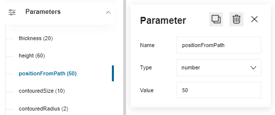
The cornice BMA does not have any component, however it has different dimension parameters to define:
- The thickness of the cornice
- The height of the cornice
- Contoured size and radius parameters for the shape
- An offset to the path if needed
Click Add new parameter on the main menu, rename the parameter (camel case) then select the type number because these are dimension parameters. Finally, define the value.
Case of Multiple Sections
In case of multiple sections, it can be useful to drive the activation of the section component, to switch from the horizontal to vertical section for example.
First, create the sectionOrientation parameter to enable the modification of the cornice orientation; this parameter
is a boolean:
- 'true' = vertical
- 'false' = horizontal
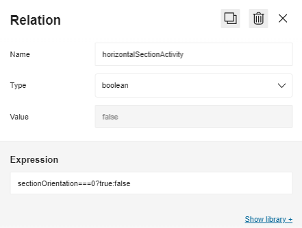
Then, create a ternary relation that will use this parameter.
In the illustration below, the relation "horizontalSectionActivity" calls the sectionOrientation parameter in the
expression sectionOrientation===0?true:false that means that if the sectionOrientation parameter is equal to 0
then horizontalSectionActivity is 'true' then 'false'.
Section Output Set
The cornice section BMA is made of one output set (named "section") that is defined by a parametric polyline, that is to say a straight line between at least two points.
All points of the set can be parametric and it is mandatory to add all the lines needed to close the section.
Example
The following output set has been defined:
- The polyline set has been renamed into "section"
- 8 points have been defined
- Point 0 and point 8 have the same coordinates to close the path
On the scene, the section is materialized by a black line with 7 points. The position of Point 0 (the start point) and Point 8 (the end point) is the origin point of the axes, on the Z-axis.
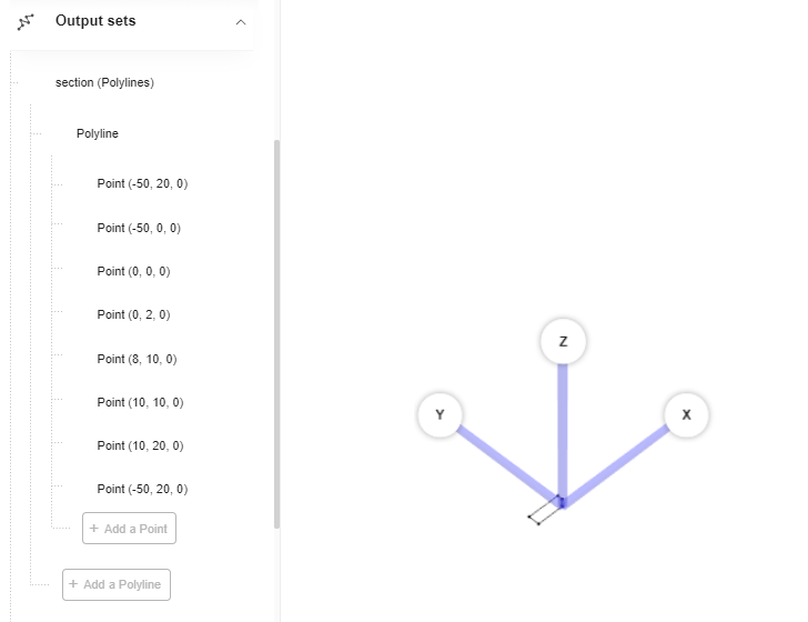
Indeed, the position and the orientation of the section is important:
- The section has to be placed from the Z-axis because it is representing the path used for the sweep function.
- Orientation is defined by the fact that sweep function is done from the right to the left of the cabinet following the top narrow/outer paths defined on it (see below Cornice Position).
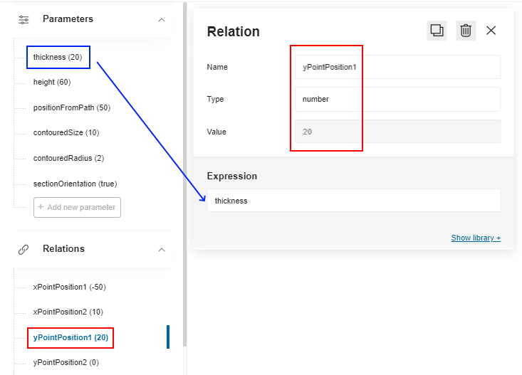
Create Relations
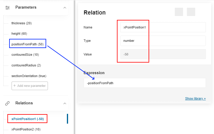
Before creating the output set you have to define relations on all the axes to create variable positions for the points of the paths.
For these relations, the formulas will use the parameters, as illustrated below.
Create the Output Set
- Click Add a polyline set and rename it into section (do not capitalize the first letter).
- Click Add a polyline.
- Click Add a point to add the first point. The default coordinates are (0, 0, 0): click the point to change them.
a. X: Slide the toggle button to Symbol and select
xPointPosition1in the Relations drop-down list. b. Y: Slide the toggle button to Symbol and selectyPointPosition1in the Relations drop-down list. c. Z: Enter 0. - Click Add a point to add the second point. Change the default coordinates into:
a. X: Select
xPointPosition1in the Relations drop-down list. b. Y: SelectyPointPosition2in the Relations drop-down list. c. Z: Enter 0. - Repeat step 4 to add five more positions with adapted coordinates.
- Repeat step 3 to add the last point with the same coordinates as the first point.
⬇️ Click here to download a BMA for cornice section with the complete definition of relations and output set.
Cornice Position
When the cornice is enabled on the
cabinet (corniceOption parameter 🔗
defined on the product), four output set must be defined on the box to define the paths for the cornice.
Each output set is a parametric polyline drawn between at least two points (start and end).
📌 The paths are defined at the box sub-assembly level in Assembly Editor, in a BMA that must have the "Box" product ID.
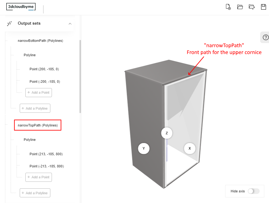
The output set will contain two paths to guide the cornice on the top of the cabinet:
- A narrowTopPath on the box front
- An outerTopPath on the box back
These paths will be also used to guide the extension of the cornice to the sides, if the leftCorniceBack
and rightCorniceBack parameters are enabled on the product. For example, the cornice will use the narrow top path and
the left point of the outter top path to extend on the left.
About the Paths
To be considered as a linear path, these output sets must:
- Have the correct name;
- Start from the right to the left: The start point (point0) is defined on the X-axis;
- Be positioned on the edge of the frame;
- Take panels into account (wall panel, cover panel, waterfall);
- Accept more than two points (especially for corner cabinets);
- Define clearly a single start point and a single end point, i.e. not be too closed from each other.
Create the Relations
Because the cornice is a linear that will be stretched dynamically along the cabinet, you have to use relations to define variable coordinates.
📌 The positions below are given for the top paths of a cornice as an example. To ease the comprehension, they do not include the cover panel parameters although they should. See below the BMA to download to get the definition relations that include the cover panels. There is no strong rule to name the relations except using camel case.
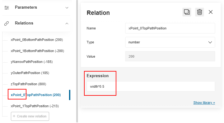
Position on the X-Axis
Create a first relation to define the position of the start point (Point 0) on the X-axis for the top path.
- Click Create new relation.
- Click the default name to display the properties.
- Rename the relation into xPoint0_TopPathPosition.
- Select number in the Type drop-down list.
- Go to the Expression field and enter a formula referring to the width parameter:
width*0.5as illustrated below. - Press Enter to save the expression and update the Value field above.
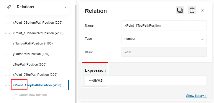
Then, repeat the whole process to define the X position of the end point (Point 1):
- Rename the relation into xPoint1_TopPathPosition
- The formula is
-width*0.5
Position on the Y-Axis
Proceed in the same way to define two variable positions on the Y-axis:
- Define a front position with the relation yNarrowPathPosition, which formula is
-depth*0.5. - Define a back position with the relation yOuterPathPosition, which formula is
depth*0.5
Position on the Z-Axis
Create a relation to define a variable vertical position: Define zTopPathPosition with the formula is height.
📌 This relation will be used by all the paths.
Create the Output Set
The next step consists in creating the output sets and defining the points between which the lines will be drawn. The coordinates of the points will be determined through the relations.
Create the first output set by clicking Add a polyline set.
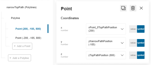
- Click the default name to access the properties and rename it into narrowTopPath.
- Click Add a polyline to specify that you will draw a line. You cannot rename the polyline.
- Click Add a point to specify the start point of the line with the following coordinates: a. X: Slide to Symbol and select the relation xPoint0_TopPathPosition. b. Y: Slide to Symbol and select the relation yNarrowPathPosition. c. Z: Slide to Symbol and select the relation zTopPathPosition.
- Repeat step 3 to create the end point of the line with the following coordinates: a. X: Select the relation xPoint1_TopPathPosition. b. Y: Select the relation yNarrowPathPosition. c. Z: Select the relation zTopPathPosition.
❗️ Repeat the whole proceeding to define the second polyline on the top back of the box; rename it into **outerTopPath **, use the same points for the X and Z and use the relation yOuterPathPosition for the Y position.
The output sets are now defined and the box is ready to receive a top cornice in the Kitchen Planner.
⬇️ Click here to download the BMA of a wall cabinet with the complete definition of paths for cornices.