Define Worktop Position
Worktops are a linear feature (like cornices or plinths) generated automatically on base cabinet, corner cabinet and high cabinets.
Worktop are not assembly component of top-assemblies. The Kitchen Application will check all the worktop products in the catalog and display all of them as possible values in the Edit panel of the top-assembly. Worktop options are editable in two different places in the kitchen planner according to the option:
- In the Edit panel of the top-assembly for basic modifications: change material, switch sides if double-sided worktop, add waterfalls, etc.
- In the Worktop editor for advanced modifications: change dimensions, cuts, edges, cut-outs, joints, etc.
➡️ See the tutorial Create a Base Cabinet 🔗 for a concrete case on worktop position management.
Because worktops are a linear feature, they are not displayed on the scene in Assembly Editor but they are generated dynamically in the Kitchen Planner from two basic information:
The worktopOption parameter 🔗
that is defined on the cabinet.
- The paths defined on the top of the box in Assembly Editor to position the worktop, as detailed hereinafter.
Definitions
| Term | Definition |
|---|---|
| Paths | Paths are lines drawn to position the worktop on the top of the box. The paths to define for a worktop are ▪️ narrowTopPath ▪️ outerTopPath |
| narrowTopPath | The name of the polyline to draw on the front of the cabinet. |
| outerTopPath | The name of the polyline to draw on the back of the cabinet. |
| Output set | A set of points to define the position of the lines. Output sets are of two types: ▪️ A polyline set, which is limited to lines defined by points only; ▪️ An edgeline set, which allow lines and circles defined by points and radiuses. |
About Paths
To define the shape of the linear features, the planner needs to know the boundaries of the cabinet. To provide these boundaries, it necessary to define some linear paths used for all linear features (worktop, wall panel, cornice, deco strip, etc.). These paths are defined at the box sub-assembly level in Assembly Editor, in a BMA that must have the "Box" product ID.
As a more detailed guideline, paths in the box assembly are composed by four output sets which are defined by a parametric polyline. All points of the set can be parametric and it is mandatory to have at least two points (start, end).
To be considered as a linear path, these output sets must:
- Have the correct name;
- Start from the right to the left: The start point (point0) is defined on the X-axis;
- Be positioned on the edge of the frame;
- Take panels into account (wall panel, cover panel, waterfall);
- Accept more than two points (especially for corner cabinets);
- Define clearly a single start point and a single end point, i.e. not be too closed from each other.
Illustration
Below is an example of output sets used to position worktops on the cabinet.
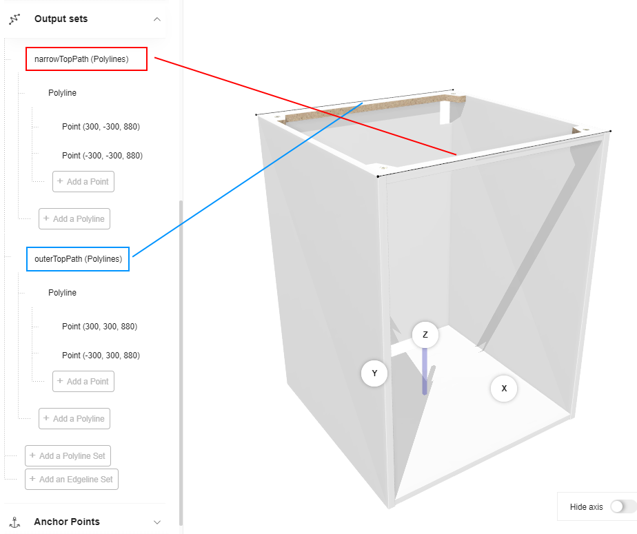
Position the Worktop
Positionning the worktop requires to define the front path (narrowTopPath) and the back path (outerTopPath). Start by creating relations to place the points dynamically, then draw the lines by creating output sets.
Create the Relations
Polylines have either fixed or variable coordinates. Because the worktop is a linear that will be stretched dynamically in any direction on all the cabinets of a same combination, you will have to define variable coordinates by using relations.
📌 The relations suggested below (and the corresponding expressions) are one possible solution. There is no strong rule to name the relations except using camel case. Expressions may be very complex to take all the components (e.g. cover panels), size variations, offsets, etc. of the assembly into account.
Position on the X-Axis
Create a first relation to define the position on the X-axis of the start point. This will place the point on the left-right axis.
- Click Create new relation.
- Click the default name to display the properties.
- Rename the relation into xPoint0_PathPosition.
- Select number in the Type drop-down list.
- Go to the Expression field.
- Enter a formula referring to the width parameter
width*0.5as illustrated below. - Press Enter to save the expression and update the Value field above.

Then, repeat the whole process to define the X position of point 1: rename the relation into xPoint1_PathPosition.
The formula is -width*0.5

Position on the Other Axes
Finally, repeat the process to define the position of points on the Y-axis and on the Z-axis:
- On the front with yPointNarrowPathPosition, which formula is
-depth*0.5 - On the back with yPointOuterPathPosition, which formula is
depth*0.5 - From the floor with zPointTopPosition, which formula is
legHeight+height

📌 The point 1 will use the same y and z relations as point 0 in the output set (see below).
Now the Relations area contains the following:

Create the Output Set
The points are created through the relations; you will now create the lines between these points and place them.
Scroll down the main menu to Output Sets and click Add a polyline set to create the first output set.
- Click the default name to access the properties and rename it into narrowTopPath.
- Click Add a polyline to specify that you will draw a line. You cannot rename the polyline.
- Click Add a point to specify the start point of the line, and repeat this step to create the final point of the
line. You cannot rename the points.

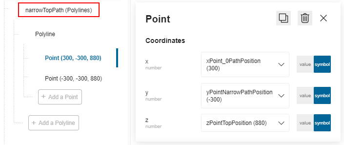
- Click Point (0, 0, 0) to access the Coordinates.
a. X: Slide to Symbol and select the relation xPoint0_PathPosition.
b. Y: Slide to Symbol and select the relation yPointNarrowPathPosition.
c. Z: Slide to Symbol and select the relation zPointTopPosition.
- Click the second point and slide to Symbol to use the relations xPoint1_PathPosition, * yPointNarrowPathPosition*, zPointTopPosition as positions.
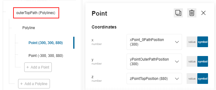
❗️ Repeat the whole proceeding to define the second polyline. Rename it into outerTopPath. Use the relation yPointOuterPathPosition for the Y position.
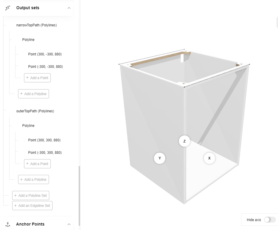
The output sets are now defined and the box is ready to receive a worktop in the Kitchen Planner.
⬇️ Click here to download the BMA of a base cabinet with the complete definition of relations and output sets.
Worktop Overhang
Worktop are defined with an overhang on the left, right, front and back sides of the cabinet.
The worktop overhang values are defined by default in the Application Distribution via a parameter,
named defaultWorktopOverhang.

➡️ See the Application Distribution Parameter
defaultWorktopOverhang🔗 for detailed information.