Define Handle Position and Orientation
The purpose of this page is to explain how to implement handle position management in the ByMe kitchen planner. There are many ways to achieve this, depending on the number of sub-assemblies building the final product and the complexity of the .BMA files. This page will deal with the most frequent handle positions.
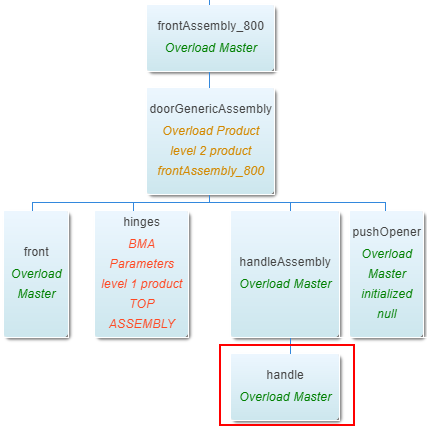
❗️ There is a high dependency with the door or drawer fronts as illustrated below. The handle product is at the lowest level in the tree that goes up to the full cabinet.
➡️ See the tutorial Create a Base Cabinet 🔗 for a concrete case on handle position management.
The example here is based on the assumption that all positions and orientations about handles are managed in a single assembly (one BMA). This assembly can be used as a component of each cabinet that need an handle.
Dimension and Offset Parameters
Before defining positions it is necessary to understand what kind of values are taken into account to calculate handle positions.

The assembly uses dimension and offset parameters that must be defined. The parameter names in the table below are suggestions; note that they are in camel case.
❗️ The same dimension and offset parameters must be defined both on the product (via 3DCloud or the code) and in the assembly.
| Parameter name | Type | Possible values | Function |
|---|---|---|---|
frontWidth | real | [0;∞] | Defines the size of the front on the X-axis of the assembly. |
frontDepth | real | [0;∞] | Defines the size of the front on the Y-axis of the assembly. |
frontHeight | real | [0;∞] | Defines the size of the front on the Z-axis of the assembly. |
xHandleOffset | real | [0;∞] | Defines the size of the gap between the edge of the door and the handle on the X-axis of the assembly. |
zHandleOffset | real | [0;∞] | Defines the size of the gap between the edge of the door and the handle on the Z-axis of the assembly. |
Handle Position on a Door Front
Possible positions of an handle on a door front are defined as illustrated below.
The type parameter must be defined on each possible handle of the handle assembly to automatically set up the correct
position. Because this type value is not an input shared to the customer it should not be set up at cabinet level.
type = 1 classic | type = 2 edge | type = 3 drop |
|---|---|---|
 |  |  |
Position and Orientation Parameters
Other parameters are taken into account for the calculation of the handle position and especially parameters that are shared and modifiable by the customer.
They must be defined on the handle assembly and at any upper level having an handle as component.
| Parameter name | Type | Possible values | Function |
|---|---|---|---|
handleLayout | integer | [0;1] | Defines whether the handle is centered on the door front or place on a side. Possible values are: ▪️ 0 = centered ▪️ 1 = sided |
side | integer | [-1;1] | Defines whether the handle is placed on the left or on the right side of the door front. Only if handleLayout is set to 1. Possible values are: ▪️ -1 = left ▪️ 1 = right |
handleOrientation | integer | [0;1] | Defines the orientation of the handle: ▪️ 0 = horizontal ▪️ 1 = vertical |
handleVerticalPosition | integer | [0;1;2] | Defines whether the vertical handle is placed on the bottom, the middle or the top of the door front. Only if handleOrientation is set to 1. Possible values are: ▪️ 0 = bottom ▪️ 1 = middle ▪️ 2 = top |
Relations
Relations are not input value from the cabinet but refer to dimension and option parameters.
Definition
Relations are expressions used to calculate dynamic values from parameters or other relations. A relation supports mathematic operators or logical tests. The result can be assigned to component properties, output set properties and anchor point properties.
Example of Relation Names
The relation names below are suggestions. There is no control on relation names in Assembly Editor, except on the camel
case.
However, it is highly recommended to compose the name of the relation on this model:
name of the component + involved parameter.
| Relation name | Type | Possible values | Function |
|---|---|---|---|
handleWidth | real | [0;∞] | Gets the size of the handle as an indirect input, which means calculated dynamically in a relation when the handle is changed. |
handleHeight | real | [0;∞] | Gets the size of the handle as an indirect input, which means calculated dynamically in a relation when the handle is changed. |
handleType | integer | [1;2;3] | Gets the type of the handle as an indirect input, which means calculated dynamically in a relation when the handle is changed. |
Expressions and Parametric Architecture
However, this set of parameter values defines only one of the possible positions. Therefore, it is necessary to define a parametric architecture to switch between various configurations.
This architecture uses expressions to calculate all the possible positions in every directions in a single relation.
Let us take the example of an horizontal classic handle placed on the top left of the door front.

The architecture suggested below (and the corresponding expressions) is one possible solution.
📌 Values in red are adjusted position due to handle type 2 itself.
On the X-Axis
On the Y-axis
The expression may depend on door position.


On the Z-axis

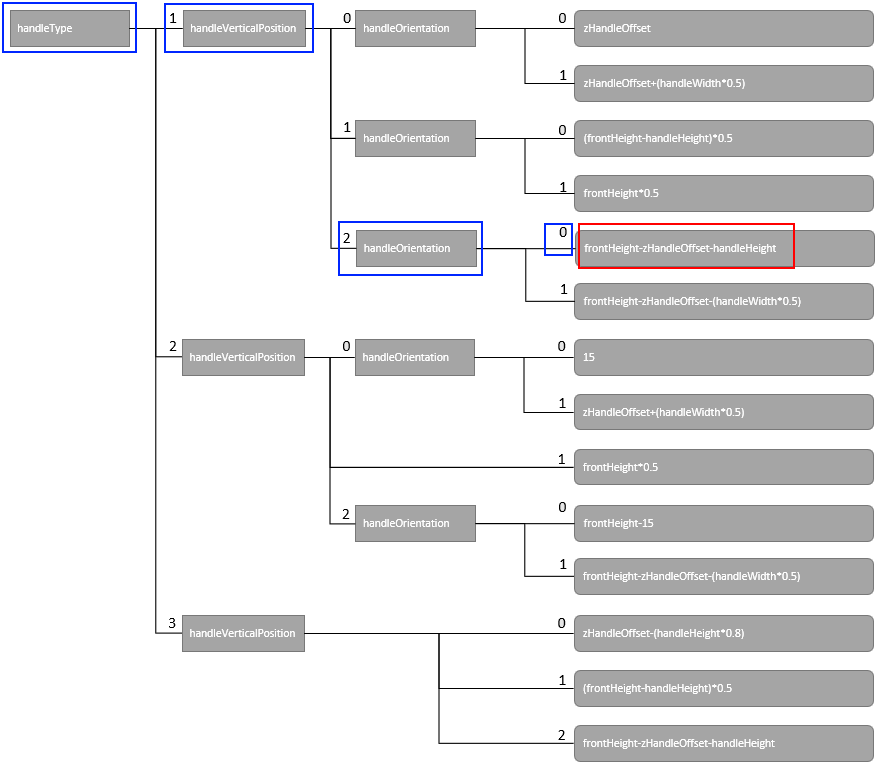
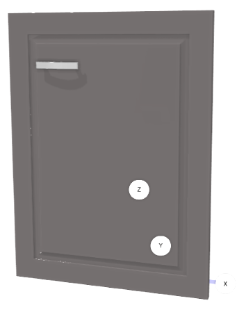
About Orientation Axes
- On a ZX-axis:
zxHandleOrientation = 0 - On a ZZ-axis:
zzHandleOrientation = 1
Ternary Relations
Ternary relations are complex expressions that perform checks before getting the value.
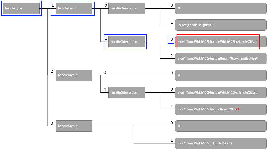
Below is a sample of a relation set containing ternary relations; this set illustrates the parametric architecture to implement to switch between various handle/front configurations. This architecture uses expressions to calculate all the possible positions in every directions in a single relation.
For example, the relation "xHandlePosition" tests the handle type and gets the handle position from it:
xHandlePosition = handleType===1?xHandleType1Position:(handleType===2?xHandleType2Position:xHandleType3Position)
This means:
"If the handle type is equal to 1, then the handle position is type 1,
else if the handle type is 2 the position type is 2, else 3".
This set is used in an handle assembly (case of an handle of type 1 on the X-axis).
📌 Note the relation naming convention used to simplify the reading of the BMA in Assembly Editor.
xHandlePosition = handleType===1?xHandleType1Position:(handleType===2?xHandleType2Position:xHandleType3Position)
xHandleType1Position = handleLayout===1?xHandleType1Layout1Position:xHandleType1Layout0Position
xHandleType1Layout1Position = handleOrientation===1?xHandleType1Layout1Orientation1Position:xHandleType1Layout1Orientation0Position
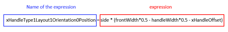
xHandleType1Layout1Orientation0Position = side*(frontWidth*0.5-handleWidth*0.5-xHandleOffset)
xHandleType1Layout1Orientation1Position = side*(frontWidth*0.5-handleHeight*0.5-xHandleOffset)
xHandleType1Layout0Position = handleOrientation===1?xHandleType1Layout0Orientation1Position:xHandleType1Layout0Orientation0Position
xHandleType1Layout0Orientation0Position = 0
xHandleType1Layout0Orientation1Position = -side*(handleHeight*0.5)
Overload Positions
Finally when all positions are calculated and defined as a result of conditions parameters, the last step consists in assigning values to the handle component. Select the Handle component in the Components list.
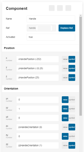
In the Position area, move the toggle button to Symbol to overload the static values with those defined by the relations:
- X: Overload with xHandlePosition.
- Y: Overload with yHandlePosition.
- Z: Overload with zHandlePosition.
In the Orientation area, move the toggle button to Symbol to overload the ZX and ZZ values:
- ZX: Overload with zxHandleOrientation.
- ZZ: Overload with zzHandleOrientation.
Result
The handle is now placed on the top left corner on the door front, and can be edited by the customer in the cabinet editor.