Define Wall Panel and Wall Edge Strip Position
In the kitchen planner, base cabinets can be enhanced with a wall panel or a wall edge strip if their back side is in contact with the wall. The wall panel option and the wall edge strip option are editable by the customer in the Edit panel.
The wall panel is a linear feature (like cornices or plinths) generated automatically on the base cabinet, from the following information:
- A material 🔗 and various options defined on the product;
- A parameter (wallPanelOption)🔗 defined on the cabinet;
- The back path defined on the box assembly.
The wall edge strip is also a linear feature, generated automatically from the following information:
- A material 🔗 and a section type🔗 defined on the product;
- A parameter (wallEdgeStripOption)🔗 defined on the cabinet;
- The back path defined on the box assembly.
❗️ Wall panels, wall edge strips and worktops 🔗 share the same output set defined on the box assembly.
Definitions
| Term | Definition |
|---|---|
| Paths | Paths are lines drawn on the box to position the wall panel or the wall edge strip. |
| Output set | A set of lines that define the position of the paths. Wall panels or wall edge strip use the output set defined for worktops on the box. This output set contains two polylines 'narrowTopPath' and 'outerTopPath'. |
| narrowTopPath | The name of the polyline drawn on the front of the cabinet. |
| outerTopPath | The name of the polyline drawn on the back of the box. |
About Paths
To define the shape of the linear features, the planner needs to know the boundaries of the cabinet. To provide these boundaries, it necessary to define some linear paths used for all linear features (worktop, wall panel, cornice, deco strip, etc.). These paths are defined at the box sub-assembly level in Assembly Editor, in a BMA that must have the "Box" product ID.
As a more detailed guideline, paths in the box assembly are composed by four output sets which are defined by a parametric polyline. All points of the set can be parametric and it is mandatory to have at least two points (start, end).
To be considered as a linear path, these output sets must:
- Have the correct name;
- Start from the right to the left: The start point (point0) is defined on the X-axis;
- Be positioned on the edge of the frame;
- Take panels into account (wall panel, cover panel, waterfall);
- Accept more than two points (especially for corner cabinets);
- Define clearly a single start point and a single end point, i.e. not be too closed from each other.
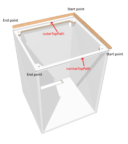
Illustration
The illustration below shows how the paths are used to extend a wall edge strip in a corner. The principle is the same for wall panels: they are generated along the back of the cabinet using the 'outerTopPath' and extended to the start point of the 'narrowTopPath'.
Create the Relations
❗️ The paths are defined at the box sub-assembly level in Assembly Editor, in a BMA that must have the "Box" product ID.
Because the wall panel or the wall edge strips are linear, you have to create relations in order to have parametric points in the output set.
📌 The relations suggested below (and the corresponding expressions) are one possible solution. In our example, they call various cover panel parameters that are not documented in this page (but available in the BMA to download below). There is no strong rule to name the relations except using camel case.
Position on the X-Axis
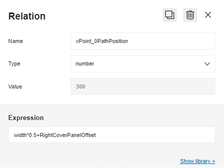
Create a first relation to define the position on the X-axis of the start point near the right cover panel.
- Click Create new relation and rename it into xPoint0_PathPosition.
- Select number in the Type drop-down list.
- Go to the Expression field and specify a formula taking the width of the box and the cover panel into account,
e.g.:
width*0.5+RightCoverPanelOffset. - Press Enter to save the expression and update the Value field above.
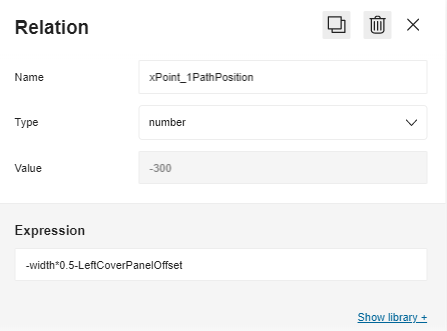
Then, repeat all the process to define the X position of point 1 near the left cover panel:
- Rename the relation into xPoint1_PathPosition;
- Specify
-width*0.5-LeftCoverPanelOffsetin the Expression field.
Position on the Y-Axis
Proceed the same way to define the position of points on the Y-axis.
- On the front, create yPointNarrowPathPosition, which formula is
-depth*0.5. - On the back, create yPointOuterPathPosition, which formula is
depth*0.5.
Position on the Z-Axis
Finally, create a position from the floor named zPointTopPosition, which formula is legHeight+height.
Now the Relations area contains the following:

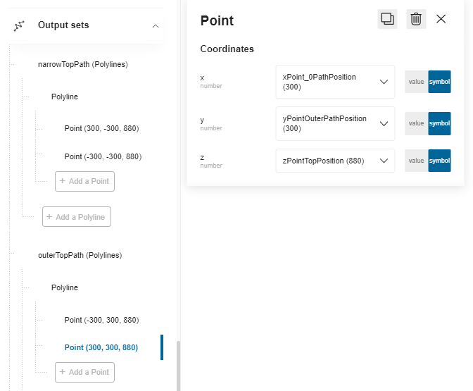
Create the Output Set
The output set on the box is made of a front path ('narrowTopPath') and a back path ('outerTopPath').
Create the narrowTopPath
Scroll down the main menu to Output Sets and click Add a polyline set to create the first output set.
- Click the default name to access the properties and rename it into narrowTopPath.
- Click Add a polyline to specify that you will draw a line. You cannot rename the polyline.
- Click Add a point to specify the start point of the line: a. X: Slide to Symbol and select the relation xPoint0_PathPosition. b. Y: Slide to Symbol and select the relation yPointNarrowPathPosition. c. Z: Slide to Symbol and select the relation zPointTopPosition.
- Click Add a point to specify the end point of the line: a. X: Slide to Symbol and select the relation xPoint1_PathPosition. b. Y: Slide to Symbol and select the relation yPointNarrowPathPosition. c. Z: Slide to Symbol and select the relation zPointTopPosition.
Create the outerTopPath
Proceed the same way to define the second polyline that you will rename into outerTopPath. Use the same relations except for the Y position: Select yPointOuterPathPosition.
The output sets are now defined and the box is ready to receive either a wall panel or a wall edge strip in the Kitchen Planner.
⬇️ Click here to download the BMA of a base cabinet with the complete definition of relations and output sets.