Define Leg Position
The purpose of this page is to explain how to implement leg position management in the ByMe kitchen planner.
Even if leg is replaceable by the customer via the edit panel, all the predefined behaviors about activation and position are hidden in the kitchen planner. To manage and maintain this configuration it is recommended to integrate the legs into a sub-assembly.
There are many ways to achieve leg positioning, depending on the number of sub-assemblies building the final product and the complexity of the .BMA files. This page will deal with the most frequent leg positions.
📌 Position management is the same whether it is a leg or a decorative leg (see at the bottom of the page).
➡️ See the tutorial Create a Base Cabinet 🔗 for a concrete case on leg position management.
The example here is based on the assumption that all positions and orientations about legs are managed in a single assembly (one BMA). This assembly can be used as a component of each cabinet that need legs.
Definitions
| Term | Definition |
|---|---|
| Leg assembly | The leg assembly is a product based on a .BMA file that defines the settings, relations and position of the legs on a box. This information is mandatory to implement the leg applicative rule. This assembly can be reused with any relevant cabinet and conversely, many assemblies with different behaviors can be created for a same cabinet. |
| Leg offsets | The distance from the legs to the edge of the box, defined on the each axis of the assembly. |
| Bottom paths | The lines defined on the bottom of the box as paths to generate the plinth. |
Add Components to the Leg Assembly
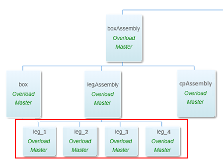
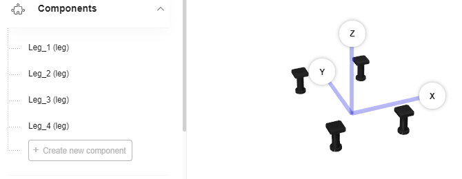
Just add one leg as component to the assembly and duplicate it as many time as needed: 4 times for a base or high cabinet, 6 times for a corner cabinet. Then, rename the leg component and its duplicates for example into "Leg_1", "Leg_2", "Leg_3", etc.
📌 The first letter of component names must be capitalized to avoid confusion with parameters.
The four legs are now part of the leg assembly.
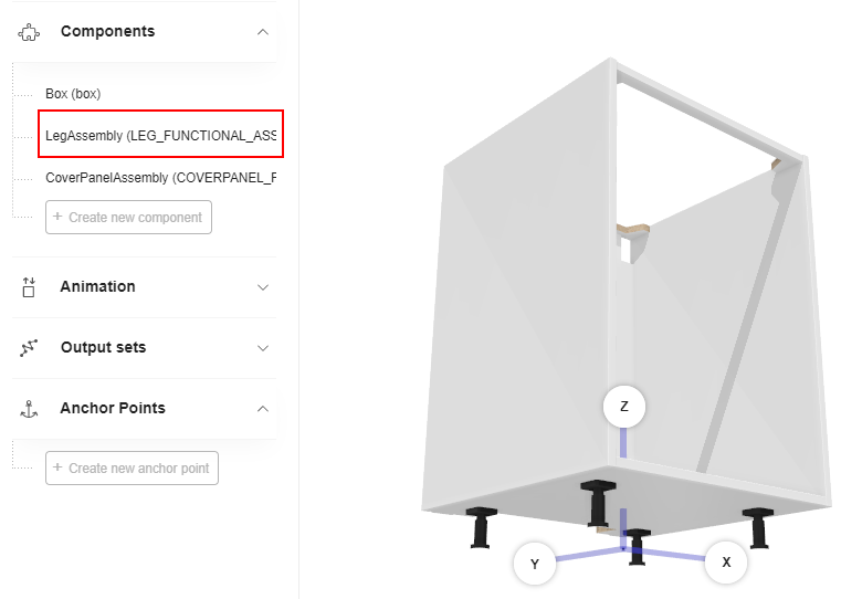
The leg assembly will be itself a component of a box/leg assembly.
Because the legs are duplicated from a same product added as component, they are identified by the same component parameter. However, each leg has its own position calculated by different relations and driven by input parameters (such as dimensions) or applicative rule parameters.
Dimension Parameters
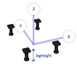
Before defining positions it is necessary to understand what kind of values are taken into account to calculate leg positions:
- The height of the leg component;
- The leg offsets (see below).
❗️ The height of the leg is very important because it impacts the distance of the box and of the cabinet from the floor. See the Applicative Rule LegHeightRule 🔗
| Parameter name | Type | Possible values | Function |
|---|---|---|---|
width | real | [0;∞] | Defines the size of the leg on the X-axis of the assembly. |
depth | real | [0;∞] | Defines the size of the leg on the Y-axis of the assembly. |
height | real | [0;∞] | Defines the size of the leg on the Z-axis of the assembly. |
The dimensions will be recovered from the component unless you create a relation to overload them in order to change the dimensions, in the perspective that the customer will choose a different leg with different dimensions in the kitchen planner.

It is possible to use the [component].[parameter] function to obtain the value dynamically.
- Click Create new relation on the main menu.
- Rename the relation into legWidth (for example).
- Select number in the Type drop-down list.
- Enter the formula above in the Expression field.
- Press Enter to save the expression and update the Value field.
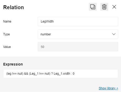
But, this function will fail in the kitchen planner if the component is undefined. Then, it is recommended to rather use a ternary relation to perform this check.
The ternary relation will check if the component exists before defining the leg width.
legWidth = "(leg!==null)?Leg_1.width:0"
This means: "If the 'leg' parameter is not 'null' then 'legWidth' is equal to the 'width' value of component 'Leg_1', else 'legWidth = 0'".
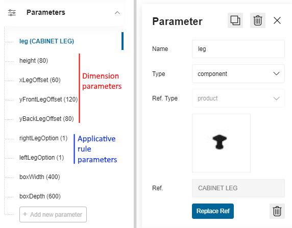
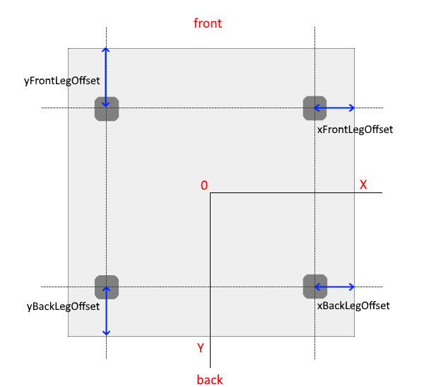
Offset Parameters
The offset is the gap from the center of the leg to the edge of the bottom of the box. You have to define as many offset parameters as there are legs in the assembly. In the table below, the parameters are for a cabinet with four legs.
| Parameter name | Type | Possible values | Function |
|---|---|---|---|
xFrontLegOffset | real | [0;∞] | Defines the distance from the leg to the front edge of the box, on the X-axis of the assembly. |
xBackLegOffset | real | [0;∞] | Defines the distance from the leg to the back edge of the box, on the X-axis of the assembly. |
yFrontLegOffset | real | [0;∞] | Defines the distance from the leg to the front edge of the box, on the Y-axis of the assembly. |
yBackLegOffset | real | [0;∞] | Defines the distance from the leg to the back edge of the box, on the Y-axis of the assembly. |
Click Add new parameter to define the first leg offset, select the type number in the drop-down list and specify the distance (in mm). Repeat the process for the other three legs.

Define Applicative Rule Parameters
The Applicative Rule Cabinet Leg Rule 🔗 handles the placement of legs under the cabinet, especially in case of corner cabinets and combination of base cabinets that share legs.
In the applicative rule, the cabinet legs positioning is managed through the three following product
parameters: leftLegOption, rightLegOption and supportLegOption.
These parameter must be defined in the assembly as well.
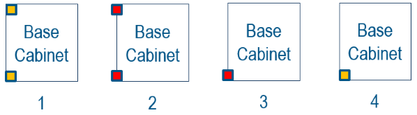
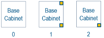
leftLegOption Definition
| Key name | Type | Possible value | Description |
|---|---|---|---|
| leftLegOption | integer | 1, 2, 3, 4 | 1: Legs #1 & #2 on the left are active and at their default position (default value) 2: Legs #1 & #2 on the left are moved outside the box on the X-axis. 3: Only leg #1 on the bottom left is moved outside the box (X direction) and leg #2 on the top left is disabled. 4: Only leg #1 on the bottom left is active at its default position and leg #2 on the top left is disabled. |
- Click Add new parameter to create the
leftLegOptionparameter. - Select integer in the Type drop-down list.
- Enter a value, 1 by default.

rightLegOption Definition
| Key name | Type | Possible value | Description |
|---|---|---|---|
| rightLegOption | integer | 0, 1, 2 | 0: Legs #3 & #4 on the right are disabled. 1: Legs #3 & #4 on the right are active (default value). 2: Only leg #4 on the top right is disabled. |
- Click Add new parameter to create the
rightLegOptionparameter. - Select integer in the Type drop-down list.
- Enter a value, 1 by default.

supportLegOption Definition
📌 This supportLegOption is for corner cabinet only.
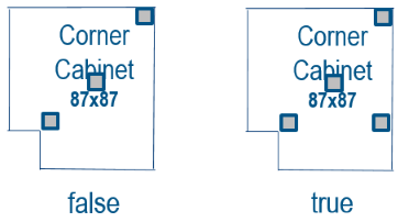
| Key name | Type | Possible value | Description |
|---|---|---|---|
| supportLegOption | boolean | true, false | true: Support leg enabled (default value). false: Support leg disabled. |
- Click Add new parameter to create the
rightLegOptionparameter. - Select integer in the Type drop-down list.
- Enter a value, true by default.

Define Relations for the Leg Options
Once the legOption parameters are defined, it is necessary to define a parametric architecture to switch between various leg configurations. You will have to create ternary relations also named "leftLegOption" and "rightLegOption".
- Click Create new relation on the main menu.
- Rename the relation into leftLegOption (for example).
- Select number in the Type drop-down list.
- Enter the formula in the Expression field: we recommend that you simply copy and paste the expression below.
- Press Enter to save the expression and update the Value field.
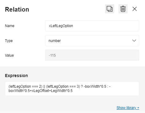
Ternary Relation to Check Leg Position
The ternary relation below checks, and changes if need be, the position of the leg.
"xLeftLegOption = (leftLegOption === 2) || (leftLegOption === 3)? -boxWidth*0.5 : -boxWidth*0.5+xLegOffset+legWidth*0.5"
Which means: "If the 'leftLegOption' parameter is equal to 2 or 3 then the 'xLeftLegOption' is equal to the half of the box width (' -boxWidth0.5'), else if 'leftLegOption' is equal to 1 then the 'xLeftLegOption' is equal to the half of the box width ('-boxWidth 0.5') + the leg offset ('+xLegOffset') + the half of the leg width ('+legWidth*0.5')".
Ternary Relation to Enable/Disable a Component
A ternary relation can also be used for a boolean parameter to manage the activation or deactivation of a component.
"activationLeg_1 = (rightLegOption === 0)? false : true"
This means: "If the 'rightLegOption' parameter is equal to 0 then the 'activationLeg_1' parameter is set to 'false', else to 'true'".
Result
The legs are now placed in an assembly that can be added as component to a box/leg assembly.
Particularities of Decorative Legs
Compared to regular leg assembly, the decorative leg assembly has a simplest definition due to a different behavior in the kitchen planner (no shared products between cabinets, same position among others). So, to avoid managing too complicated assembly when it is not needed it is advised to create an assembly dedicated to decorative legs.
This decorative leg assembly will be similar to a classic leg assembly with the following particularity that:
- It is made of only two decorative leg products as components (instead of a set of four legs by default);
- The only possible position for decorative legs is the front of the cabinet.
There are no mandatory parameter specific to decorative legs at assembly level. However, to avoid impacting the overload chain from cabinet product, it is highly recommended to use a leg parameter name to define a parametric decorative leg component.
The usage of a dedicated assembly for two legs needs to switch the assembly dynamically in the kitchen planner when the customer chooses a decorative leg. To achieve that, it is advised to set a product rule of type "chain" that will define the leg assembly to use for each leg.