Define Plinth Position
The purpose of this page is to explain how to implement plinths position management in the ByMe kitchen planner.
The plinth is a linear feature that is added dynamically to the cabinet in the kitchen planner from the following information:
- The plinth section BMA,
- The position of the legs on the box assembly,
- Front and back paths defined on the box assembly,
- A parameter (
plinthOption)🔗 enabled on the cabinet.
❗️ Plinths strongly depend on legs. See Define Leg Position 🔗 before positioning plinths.
📌 Position management is the same whether it is a plinth or a decorative plinth (see at the bottom of the page).
Definitions
| Term | Definition |
|---|---|
| Plinth section | A BMA defining the section of the (decorative) plinth, i.e. a polyline or a polyedge that defines the shape of the plinth. |
| Leg offsets | The distance from the legs to the edge of the box, defined on the each axis of the assembly. |
| Bottom paths | The lines defined on the bottom of the box as paths to generate the plinth. |
The Plinth Section BMA
The plinth BMA is actually just the definition of the plinth cross section; there is no component in the plinth BMA.
In other words, this BMA is a polyline or a polyedge that defines the shape of the plinth. Your convention may be to build the edges in anti-clockwise orientation; in this case, the matter of the plinth would be on the left of the edge.
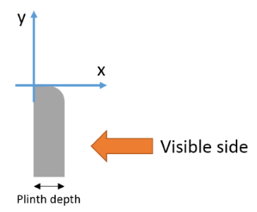
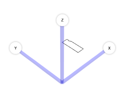
The cross section shape shall be defined in XY plan and oriented as illustrated below. The position of the origin of the plinth is also important and by convention defined on the top, back of the plinth (when the plinth is placed on the leg). When the plinth position is 'onFrame' or 'onFront' the plinth is automatically moved by using the depth of the plinth product.
Plinth Parameters
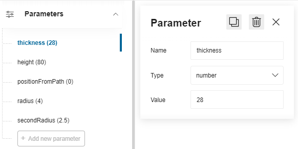
The plinth BMA does not have any component, however it has different dimension parameters to define:
- The thickness of the plinth
- The height of the plinth
- A radius that corresponds to the leg diameter
- An offset to the path if needed
Click Add new parameter on the main menu, rename the parameter (camel case) then select the type number because these are dimension parameters. Finally, define the value.
Create the Section
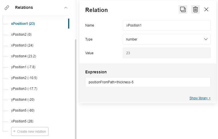
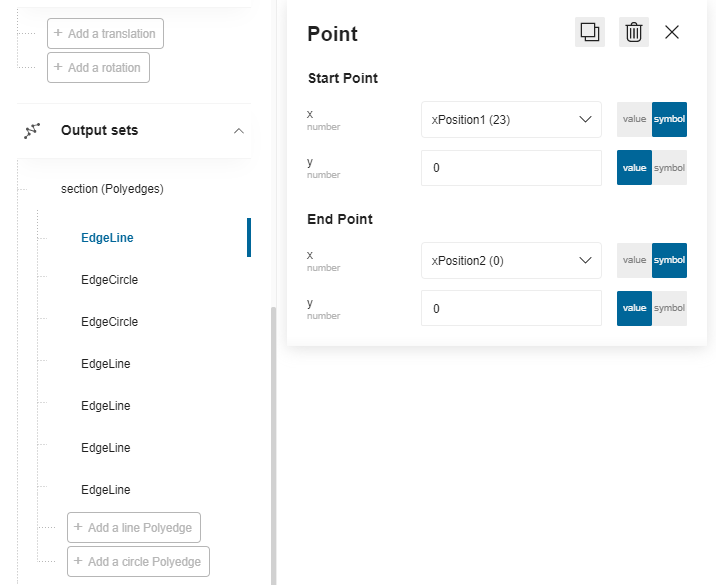
The section of the plinth is a polyedge output set that combines edge lines and edge circles to draws a closed shape with the molding specificities of the plinth.
Before creating the output set you have to define relations that the points will use. For the position on the X-axis, specify formulas that use the parameters, while the positions on the Y-axis will have fixed values.
The vertical position of the section depends on the leg height.
Create the output set to reflect the shape of the plinth.
⬇️ Click here to download a BMA for cross section with the complete definition of relations and output set.
Leg Position and Plinth
When the plinth is placed on the legs ('onLeg' parameter 🔗 defined on the product), the leg offset values must be taken into account.
- The front offset is defined at a distance from the box front to the back side of the plinth and the front side of the leg.
- The back offset is defined at a distance from the back of the box to the back side of the plinth and the front side of the leg.
- The side offset is defined at a distance from the left or right sides of the box to the back side of the plinth and the front side of the leg.
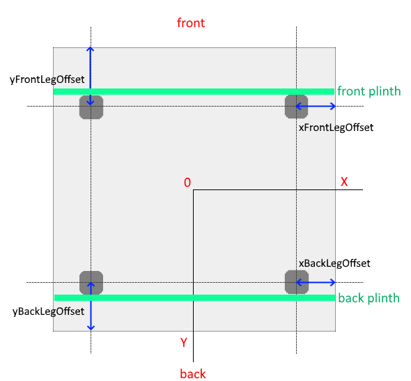
📌 For the front leg offset: If the leg offset is null or equal to 0, a default minimum offset equal to the depth of the plinth will be applied in order to align the front of the plinth with the front of the box (and thus avoid exceeding the box of the cabinet). As usual, these offset parameter values are defined on the cabinet and should be overloaded through all the upper sub-assemblies to update the leg positions.
Define the Path on the Box
The paths are lines under the box placed to guide the linear. They are defined at the box sub-assembly level in Assembly Editor, in a BMA that must have the "Box" product ID.
As a more detailed guideline, paths in the box assembly are composed by two output sets which are defined by a parametric polyline. All points of the set can be parametric and it is mandatory to have at least two points (start, end).
To be considered as a linear path, these output sets must:
- Have the correct name;
- Start from the right to the left: The start point (point0) is defined on the X-axis;
- Be positioned on the edge of the frame;
- Take panels into account (wall panel, cover panel, waterfall);
- Accept more than two points (especially for corner cabinets);
- Define clearly a single start point and a single end point, i.e. not be too closed from each other.
Paths for a Base Cabinet
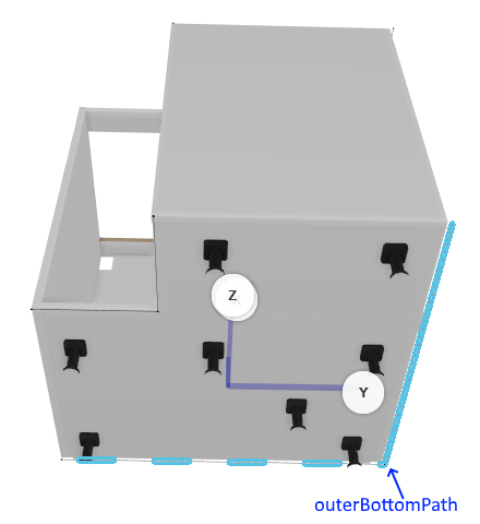
For a base cabinet, you have to define a narrowBottomPath and an outerBottomPath, as illustrated below.
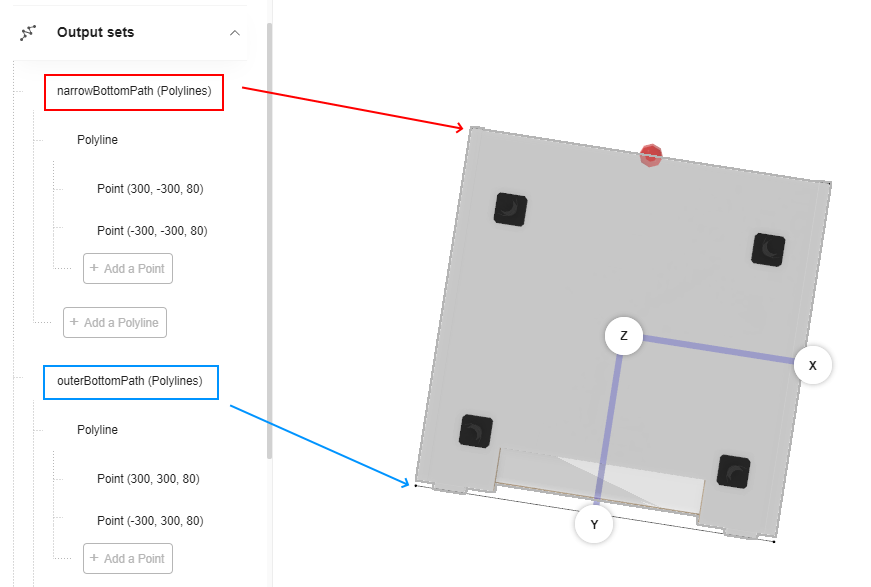
narrowBottomPath "Point 0" and "Point 1" must correspond to the 2 corners at the front of the cabinet. You can use relations to adapt their positions to any variation.
outerBottomPath "Point 0" and "Point 1"must correspond to the 2 corners at the back of the cabinet. You can use relations to adapt their positions to any variation.
➡️ See Position the Worktop 🔗 to have detailed information on the process to create relations and output sets. Defining the paths for the plinths on the bottom of the box is the same than defining the paths on the top for the worktop.
Paths for a Corner Cabinet
narrowBottomPath
"Point 0", "Point 1" and "Point 3" must correspond to the inside corners at the front of the cabinet.
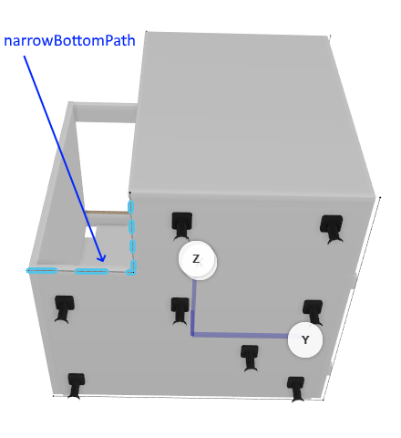
outerBottomPath
"Point 0", "Point 1" and "Point 3" must correspond to the inside corners at the back of the cabinet.
Result
The plinth position is now defined and it can be generated on cabinets.
⬇️ Click here to download a box BMA with the paths for the plinth
Particularities of Decorative Plinths
Like usual about legs, legs position and legs type, the kitchen planner needs to set up different leg configurations depending on the situation, including for decorative legs. Kitchen planner applicative rule can manage different use cases.
📌 Because legs are added as substitution of regular legs it is advise to add the decorative leg assembly as a second leg assembly of the box. To set up, it is possible to use a product rule to activate automatically this second assembly (see the product rule for decorative legs 🔗 as a similar sample).
➡️ See Applicative Rule Definition In 3D Cloud in Set Up Decorative plinths 🔗
leftLegOption and rightLegOption Definition
left/rightLegOption parameters are based on the same structure:
leftLegOption = 1: On left side, front and back legs are straight legs.
rightLegOption = 1: On right side, front and back legs are straight legs.

leftLegOption = 2: On left side, front leg is a straight leg and back leg is disabled.
rightLegOption = 2: On right side, front leg is a straight leg and back leg is disabled.

leftLegOption = 3: On left side, front and back legs are corner legs.
rightLegOption = 3: On right side, front and back legs are corner legs.

leftLegOption = 4: On left side, front leg is a corner leg and back leg is disabled.
rightLegOption = 4: On right side, front leg is a corner leg and back leg is disabled.

leftLegOption = 5: On left side, front leg is a corner leg and back leg is a straight leg oriented to Y direction.
rightLegOption = 5: On right side, front leg is a corner leg and back leg is a straight leg oriented to Y direction.

leftLegOption = 6: On left side, front leg is a straight and back leg is a corner leg.
rightLegOption = 6: On right side, front leg is a straight and back leg is a corner leg.

leftLegOption = 7: On left side, front leg is a corner leg and back leg is a straight leg oriented to X direction.
rightLegOption = 7: On right side, front leg is a corner leg and back leg is a straight leg oriented to X direction.

left/right/backAdditionalLegPosition Definition
To manage additional leg activation and position on the same parameter, left-/right-/
and backAdditionalLegPosition parameters can be set by code with the real distance between the two cabinets to set the
correct leg position or with "-1" which means that the leg is deactivated.
If backAdditionalLegPosition = -1 then additional leg is deactivated on back side. Else, backAdditionalLegPosition = [0 ;∞] defines the real position of the leg on X direction.
If leftAdditionalLegPosition = -1 then the additional leg is deactivated on the left side. Else, leftAdditionalLegPosition = [0 ;∞] defines the real position of the leg on Y direction.
If rightAdditionalLegPosition = -1 then the additional leg is deactivated on the right side. Else, rightAdditionalLegPosition = [0 ;∞] defines the real position of the leg on Y direction.