Define Worktop Cut-Out Position
Cut-outs in the worktop are necessary to place sinks, taps and cooktops among others. In the kitchen planner, the customer has the choice between two shapes for a cut-out: rectangle (including square) or circle. These shape directly correspond to the paths that you will define on the product.
Although the sink, the tap or the cooktop will be inserted in a worktop, the path for the cut-out shall not be defined on the cabinet but on the product itself (e.g. on the sink or on the cooktop).
❗️ The present page will take a sink and a tap as example, but the logic is the same for a cooktop or any object to place in a cut-out.
Definitions
| Term | Definition |
|---|---|
| Paths | Paths are lines drawn to position the sink in the worktop cut-out. The paths to define for a sink are ▪️ narrowTopPath ▪️ outerTopPath |
| narrowTopPath | The name of the polyline to draw on the front of the cabinet. |
| outerTopPath | The name of the polyline to draw on the back of the cabinet. |
| Output set | A set of points to define the position of the lines. Output sets are of two types: ▪️ A polyline set, which is limited to lines defined by points only; ▪️ An edgeline set, which allow lines and circles defined by points and radiuses. |
About Paths
To define the shape of the cut-out, the planner needs to know the boundaries of the object that will be inserted in the cut-out. To provide these boundaries, it necessary to define some paths at the product or sub-assembly level in Assembly Editor.
As a more detailed guideline, paths in the box assembly are composed by output sets which are defined by a parametric polyline. All points of the set can be parametric and it is mandatory to have at least two points (start, end).
To be considered as a linear path, these output sets must:
- Have the correct name;
- Start from the right to the left: The start point (point0) is defined on the X-axis;
- Be positioned on the edge of the frame;
- Take panels into account (wall panel, cover panel, waterfall);
- Accept more than two points (especially for corner cabinets);
- Define clearly a single start point and a single end point, i.e. not be too closed from each other.
Illustration
Below is an illustration of output sets defined on a sink and on a tap to position them into a worktop cut-out.

Create Paths for Cut-Outs
To define the shape of the cut-out feature (even for a sink, a hob or a tap), the kitchen planner needs to know the boundaries of the cutting area. To provide these boundaries, it necessary to define the paths used to cut the worktop.
Cut-outs are defined as an output set and can be a either a polyline or a polyedge. A polyedge is recommended.
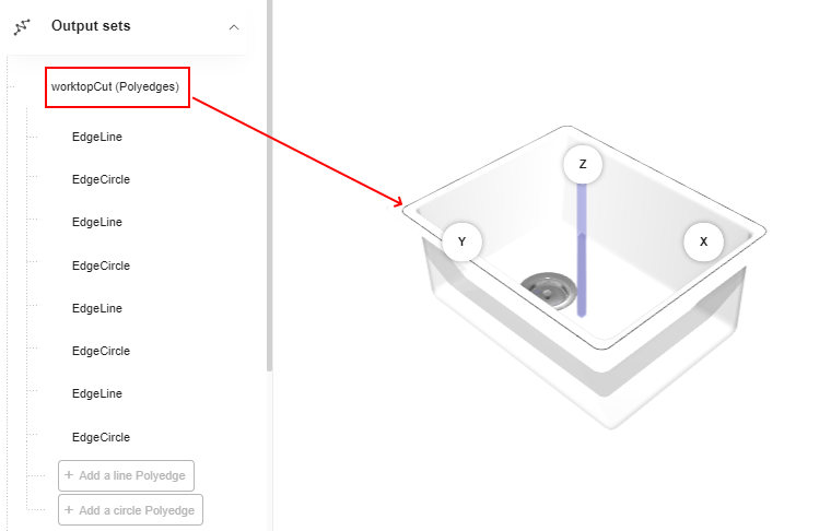
❗️ Like every output set, the shape must have an appropriate name: in this case the required name is "worktopCut".
❗️ The full depth products, like full depth sinks, are particular products mounted between worktops. No cut-out should be defined for these products or the planner won’t behave as expected.
Output Set for a Sink
Because the sink has non-resizable dimensions, you do not need to define variable positions through relations.
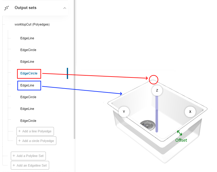
Simply create a polyedge to define the lines and curves required to duplicate the sink shape for the cut-out. You will have to alternate an edgeline and an edgecircle to draw the shape, as illustrated below. In case of fully round sinks, define edgecircles only.
- Each line has a start and an end point
- Each circle has a radius and a clockwise in addition to both start and end points
Click Add an edgeline set in the main menu and rename it into worktopCut as recommended.
Define the First Edgeline
❗️ Sink can be either top-mounted or under-mounted. Therefore, an offset may apply from the sink edges to the cut-out edges. Take it into account when specifying the coordinates.

- Click Add a line polyedge to add the first line.
- Enter the coordinates of the Start Point: a. X: Enter the distance from the origin point to the internal left corner. b. Y: Enter the distance from the origin point to the line.
- Enter the coordinates of the End Point: a. X: Enter the distance from the origin point to the internal right corner. b. Y: Enter the distance from the origin point to the line.
Define the First Edgecircle

- Click Add a circle polyedge to add the first circle.
- Enter the coordinates of the Start Point: a. X: Enter the position of the first line end point. b. Y: Enter the position of the first line end point.
- Enter the coordinates of the End Point: a. X: Enter the distance from the origin point to the external right corner. b. Y: Enter the distance from the origin point to the internal right corner.
- Enter a radius to draw the circle: e.g. 15 degrees.
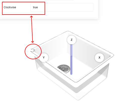
- Define the direction of the circle: Set the Clockwise to False because this circle is drawn anti-clockise.
Define the Other Lines and Circles
Define the other circles by taking this into account:
- Each start point of a circle/line is the end point of the previous line/circle
- Change the direction of each circle to focus their center to the center of the sink:
- Set the Clockwise to False to draw an anti-clockise circle
- Set the Clockwise to True to draw a clockise circle
⬇️ Click here to download a BMA for sink cut-out with the complete definition of output set.
Output Set for a Tap
Because the tap has fixed dimensions, you do not need to define variable positions through relations.
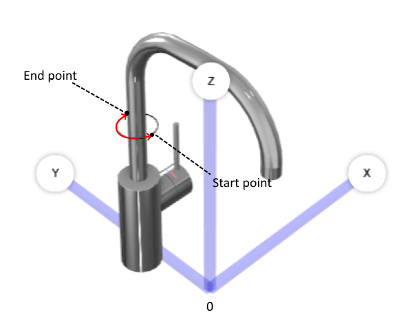
You just need to create a polyedge to define a circle around the tap for the cut-out. We recommend that you build the circle from two semi circles, as illustrated below:
Click Add an edgeline set in the main menu and rename it into worktopCut as recommended.
Define the First Edgecircle
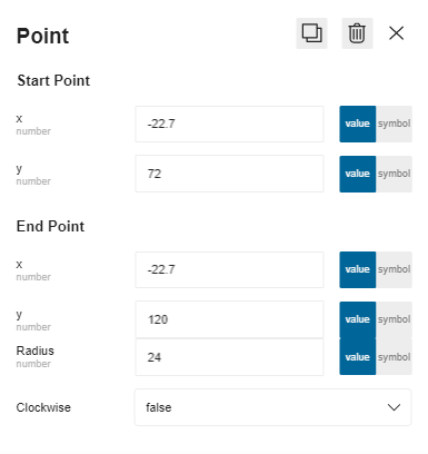
- Click Add a circle polyedge to add the first semi circle.
- Enter the coordinates of the Start Point: a. X: Enter the position from the origin point to the left external edge of the tap. b. Y: Enter the position from the origin point to the front external edge of the tap.
- Enter the coordinates of the End Point: a. X: Enter the same position as the start point. b. Y: Enter the position from the origin point to the back external edge of the tap.
- Enter a radius to draw the circle: e.g. 24 degrees.
- Define the direction of the circle: Set the Clockwise to False because this circle is drawn anti-clockise.
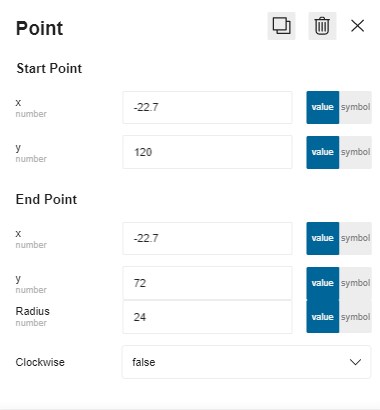
Define the Second Edgecircle
Define the second semi circle by taking this into account:
- Each start point has always the same position on the X-axis.
- Reverse the position on the Y-axis.
⬇️ Click here to download a BMA for tap cut-out with the complete definition of output set.